Separable support for control valve

A technology for separating brackets and control valves, applied in the field of detachable brackets, can solve problems such as waste and bracket scrapping, and achieve the effects of prolonging service life and reducing costs

Inactive Publication Date: 2016-06-01
刘福太
View PDF0 Cites 0 Cited by
  • Summary
  • Abstract
  • Description
  • Claims
  • Application Information

AI Technical Summary

Problems solved by technology

The bracket is generally used as a whole from top to bottom, but the disadvantage of the overall setting is that if any part of the bracket is damaged, the whole bracket will be scrapped, which will cause waste

Method used


Image

  • Separable support for control valve
  • Separable support for control valve

Examples


Embodiment l

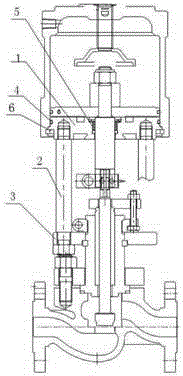
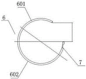
[0015] As shown in l and figure 2 As shown, the detachable support for the control valve has a cylinder snap ring 6, which is arranged between the cylinder and the valve body, including the upper part of the support l, which is movably connected with a left-right symmetrical support rod 2, and the upper part of the support l is two There is a cylinder snap ring connecting the detachable bracket used for the control valve and the cylinder at the end, the cylinder snap ring 6 is an unsealed plastic or rubber ring, the width of the ring is 5~8cm and the horizontal diameter is used as the dividing line Divided into an upper half ring 601 and a lower half ring 602, the upper half ring 601 is a circular arc segment of 125~160°, the lower half ring 602 is a semicircular arc, and the opening side of the lower half ring 602 is provided with a groove bayonet 7. There is a hole in the center of the upper part l of the bracket, and the bracket rod 2 passes through the bracket installation...

Embodiment 2

[0018] As shown in Figure 1, the upper part of the bracket l and the bracket rod 2 are connected by bolts. The way of bolt connection is relatively stable, so it is a better way for the connection of the upper part 1 of the support and the support rod 2.

[0019] Two ends of the upper part of the bracket are provided with bracket O-ring placement holes. The setting of the support O-ring placement hole is to prevent the support O-ring, so as to ensure the sealing of the entire cylinder interior.

[0020] The outside of the inner wall of the hole is provided with a push rod bushing 5 . The push rod of the cylinder actuator needs to pass through the hole of the detachable bracket for the control valve, and in order to seal the push rod and the hole, a push rod bushing needs to be provided.

[0021] The support rod 2 on the left side of the upper part of the support is provided with a slide bar, and the support rod 2 on the right side of the upper part of the support is provided...


PUM


Abstract

The invention discloses a separable support for a control valve. The separable support is provided with air cylinder clamping rings which are arranged between an air cylinder and a valve body. An upper support part is included and movably connected with support rods in bilateral symmetry. The air cylinder clamping rings capable of connecting the separable support for the control valve with the air cylinder are arranged at the two ends of the upper support part, a hole is formed in the center of the upper support part, and the support rods are arranged in support mounting holes in a flange valve cover of the valve body in a penetrating manner. The upper support part and the support rods are movably connected, it can be guaranteed that the upper support part and the support rods are separated, and the hole formed in the center of the upper support part allows a push rod in the air cylinder to conveniently slide therein. The upper support part and the support rods are arranged to be movably connected, and one of the upper support part and the support rods can be replaced with a new component when damaged, so that the service life of the components is prolonged, and cost is reduced.

Description

technical field [0001] The invention relates to a bracket, in particular to a detachable bracket for supporting a valve and used for controlling a valve. Background technique [0002] The actuator used for the control valve needs to be connected with the control valve body with a bracket for use. The support is generally used as a whole, but the disadvantage of the overall arrangement is that if any part of the support is damaged, the whole support will be scrapped, which will cause waste. Contents of the invention [0003] The invention provides a detachable bracket, the upper part of the bracket and the bracket rod are detachable and not fixedly connected, prolonging the service life of each component and reducing the cost. [0004] The purpose of the present invention is achieved through the following technical solutions: [0005] The detachable bracket for the control valve, with a cylinder snap ring, is set between the cylinder and the valve body, including the uppe...

Claims


Application Information

Patent Timeline
Patent Type & Authority Applications(China)
IPC IPC(8): F16K51/00F16K31/12
Inventor 刘福太
Owner 刘福太
Why Eureka
Try Eureka