
Lifting device

A lifting device and lifting bracket technology, which is applied to furniture parts, household appliances, furniture accessories, etc., can solve problems such as unfavorable disassembly and maintenance, unstable positioning, and short service life, and achieve simplification of the overall structure and easy disassembly and assembly. With the effect of convenient maintenance and low cost

Inactive Publication Date: 2016-06-08
GUANGZHOU FOCUS DIGITAL TECH
View PDF6 Cites 1 Cited by
  • Summary
  • Abstract
  • Description
  • Claims
  • Application Information

AI Technical Summary

Problems solved by technology

[0002] In the prior art, the general lifting device is mainly controlled by the motor, cylinder or oil cylinder, the structure is too complicated, the cost is high, and it is not conducive to disassembly and maintenance; while the manual lifting device is usually unstable in positioning, easily damaged, and has a short service life.

Method used


Image

  • Lifting device
  • Lifting device
  • Lifting device

Examples


Embodiment Construction

[0025] Below in conjunction with accompanying drawing and embodiment the present invention will be further elaborated, and the direction of the present invention is based on figure 1 prevail.

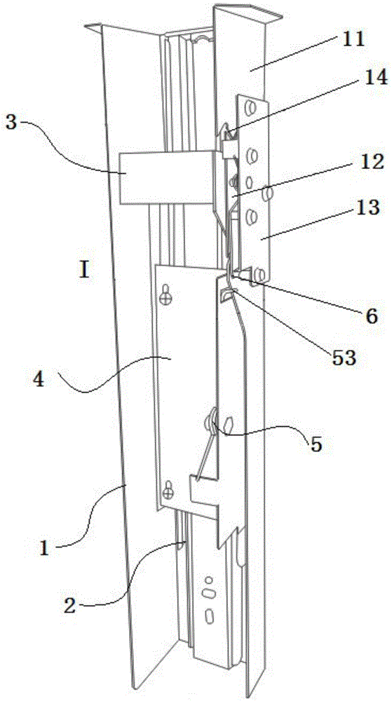
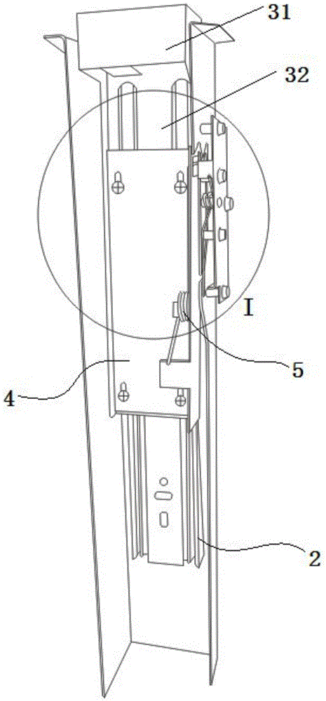
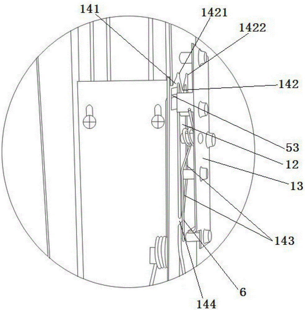
[0026] combine Figure 1 to Figure 5 As shown, a lifting device includes a support base 1, a slide rail assembly 2, and a lifting bracket 3. The slide rail assembly 2 is fixed on the support base 1, and the lifting bracket 3 is arranged on the slide rail assembly 2 to move up and down with the slide rail assembly 2. slide.

[0027] The support seat 1 is a C-shaped channel steel, one side of which includes a side plate 11, a splicing plate 12 and a fixed plate 13, the side plate 11 has an inclined section 111, the transition from the bottom of the side plate 11 to the top through the inclined section 111, and the upper side of the side plate 11 is set There is a gap, the splicing plate 12 is combined with the side plate 11 in a non-contact manner through the gap, and the fixing plate 1...


PUM


Abstract

The invention discloses a lifting device. The lifting device comprises a bearing seat, a sliding rail assembly and a lifting bracket, wherein the sliding rail assembly is fixed to the bearing seat and comprises a fixed sliding rail and a movable sliding rail; the lifting bracket is fixed to the movable sliding rail and slides up and down along the fixed sliding rail along with the movable sliding rail; the lifting bracket is provided with a guide strip; a guide channel for the guide strip to slide is formed in one side surface of the bearing seat; and the lifting bracket is lifted and positioned through the sliding of the guide strip in the guide channel. According to the lifting device, the guide strip and the guide channel are adopted; during ascending, a user manually pulls a sliding device upwards, the guide strip slides to a highest point along the guide channel, and the user stops application of force, so that the sliding device can be accurately positioned at a predetermined height; during descending, the guide strip can descend to an initial position along the guide channel only by applying upward pull force; through simple design of the guide strip and the guide channel, the lifting is realized; and the process operation is simple.

Description

technical field [0001] The invention relates to the technical field of machinery, in particular to a manually operated lifting device. Background technique [0002] In the prior art, the general lifting device is mainly controlled by the motor, cylinder or oil cylinder, the structure is too complicated, the cost is high, and it is not conducive to disassembly and maintenance; while the manual lifting device is usually unstable in positioning, easily damaged, and has a short service life. . Contents of the invention [0003] In order to overcome the above-mentioned problems in the prior art, the present invention provides a manually operated lifting device with simple structure, not easy to be damaged, easy to install and maintain. [0004] The technical solution of the present invention is: a lifting device, including a support base, a slide rail assembly, and a lifting bracket, the slide rail assembly is fixed on the support base, the slide rail assembly includes a fixed...

Claims


Application Information

Patent Timeline
Patent Type & Authority Applications(China)
IPC IPC(8): A47B96/00
CPCA47B96/00A47B2220/0002
Inventor 崔金敏
Owner GUANGZHOU FOCUS DIGITAL TECH
Learn More