
A kind of pcie card fixing device and fixing method

A card fixing and fixing bracket technology, which is applied in the field of PCIe card fixing devices, can solve the problems of not being able to adapt to the effective fixing of PCIe cards, and achieve the effects of saving maintenance time, saving materials, and good heat dissipation

Active Publication Date: 2022-04-26
INSPUR SUZHOU INTELLIGENT TECH CO LTD
View PDF4 Cites 0 Cited by
  • Summary
  • Abstract
  • Description
  • Claims
  • Application Information

AI Technical Summary

Problems solved by technology

[0005] In order to overcome the deficiencies in the above-mentioned prior art, the present invention provides a PCIe card fixing device to solve the problem that the traditional PCIe card bracket cannot adapt to the current full-height and full-length series of PCIe cards for effective fixing thereof

Method used


Image

  • A kind of pcie card fixing device and fixing method
  • A kind of pcie card fixing device and fixing method
  • A kind of pcie card fixing device and fixing method

Examples


specific Embodiment approach 1

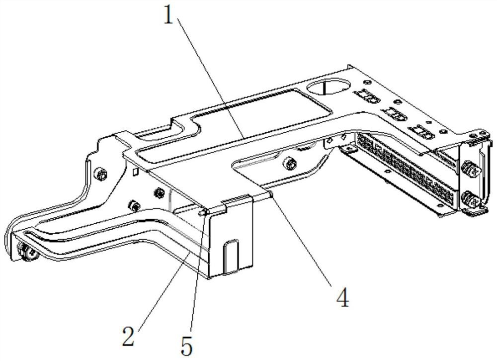
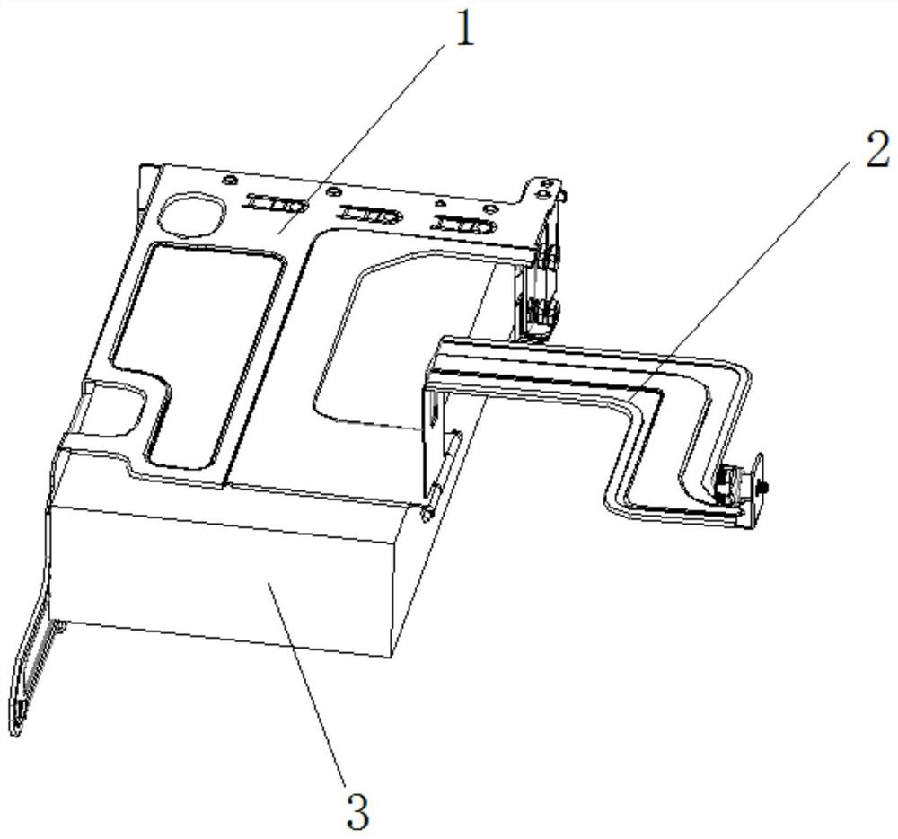
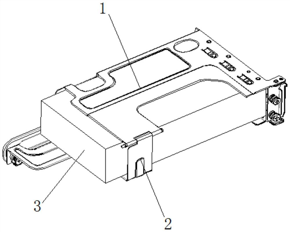
[0030] like Figure 1 to Figure 5As shown, the present invention provides a PCIe card 3 fixing device, which is composed of a fixed bracket 1 and a rotating support plate 2. One end of the rotating support plate 2 is rotatably installed at the rear of the fixing bracket 1, and the rotating support plate The other end of the board is provided with a locking assembly for fastening on the fixed bracket 1. The front of the fixed bracket 1 is provided with a card slot. Before the PCIe card 3 is placed in the fixed bracket 1, turn the rotating support plate 2 to make the fixed bracket The right side of 1 forms an opening. When the PCIe card 3 is placed in the fixed bracket 1, slide the front part of the PCIe card 3 through the card slot. After the PCIe card 3 is placed in the fixed bracket 1, turn the rotating support plate 2 and lock it The assembly is fastened on the fixing bracket 1, and at this time, the bottom of the PCIe card 3 is only supported by the rotating support plate 2...

specific Embodiment approach 2

[0033] On the basis of Embodiment 1, this specific embodiment provides a fixing method for fixing full-length and full-height series PCIe cards 3 using a PCIe card 3 fixing device, including the following steps:

[0034] A1. Rotate the rotating support plate 2 at a certain angle to a position where its bottom is higher than the top plate 12, forming an opening on the right side of the fixed bracket 1;

[0035] A2. Put the riser card into the opening on the right side, and fix the riser card to the riser card installation position 111 of the left side plate 11;

[0036] A3. Slide the PCIe card 3 from the right side along the card slot until the left side of the PCIe card 3 is inserted into the adapter card;

[0037] A4. Rotate the rotating support plate 2 and connect the rotating support plate 2 to the fixed bracket 1 with thumb screws 25 .


PUM


Abstract

The invention provides a PCIe card fixing device and a fixing method, the adopted scheme is: comprising a fixed bracket and a rotating support plate, one end of the rotating support plate is rotatably installed on the rear of the fixing bracket, and the rotating The other end of the support plate is provided with a locking assembly for fastening on the fixed bracket, and the front part of the fixed bracket is provided with a card slot; when the rotating support plate is opened, it can be rotated to the top of the fixed bracket, so that the fixed bracket The right side forms an opening, allowing the front of the PCIe card to slide in through the card slot. When the rotating support plate is closed, the locking component on the rotating support plate is fastened to the fixed bracket, and at this time, the bottom of the PCIe card can only pass through the slot. The rotating support plate and the bottom of the slot are supported. By adding a rotating support plate in the narrow space on the side of the tail of the PCIe card, the tail of the PCIe card can be supported and fixed in the up and down and left and right directions, and it is also convenient for users to quickly remove and fix the PCIe card, saving maintenance time.

Description

technical field [0001] The invention relates to the field of computer server equipment, in particular to a PCIe card fixing device. Background technique [0002] Digital industries such as autonomous driving, smart city, smart medical care, and smart transportation led by 5G cloud computing AI have higher and higher computing performance requirements for servers. In order to meet the high computing performance requirements of the current 5G cloud computing AI, servers have higher and higher configuration performance requirements for PCIe cards. Traditional small PCIe cards can no longer meet the needs of high-performance computing. Full-height and full-length PCIe cards have gradually become the mainstream configuration of servers. [0003] However, the configuration of full-height and full-length PCIe cards will also bring some risk points for testing by server organizations. A single full-height and full-length PCIe card weighs about 1.0KG. After being installed with a f...

Claims


Application Information

Patent Timeline
Patent Type & Authority Patents(China)
IPC IPC(8): G06F1/18
CPCG06F1/185
Inventor 艾波
Owner INSPUR SUZHOU INTELLIGENT TECH CO LTD
Learn More