Injection mould for connecting rod

A technology for injection molds and connecting rods, applied in the field of injection molds with double-layer cavities, can solve problems such as affecting efficiency, inconvenient demoulding, and increasing corporate burdens, achieving improved efficiency, reduced flow resistance, and convenient cleaning and mold taking. Effect

Active Publication Date: 2014-11-19
SUZHOU LASERHOWER PRECISION CASTING
View PDF4 Cites 0 Cited by
  • Summary
  • Abstract
  • Description
  • Claims
  • Application Information

AI Technical Summary

Problems solved by technology

In terms of cavity design, although it is possible to design a better cavity according to the shape of the connecting rod to be processed, in some small aspects such as some connecting rods, it is usually necessary to open some holes and especially like Some complex shapes of the connecting rod involved in the present invention usually cannot be completed in one casting in the mold cavity, but need to be processed through other steps after molding, which is very troublesome to operate; and in terms of runner design, Due to some unreasonable gate designs usually adopted, such as the slow inflow of the wax liquid in the cavity due to the large flow resistance, which affects the efficiency, in terms of the mold taking device, some traditional molds usually suffer from poor design. It is not easy to demould and reduce efficiency. To sum up some shortcomings of the special injection molds for processing connecting rods in the same field, it can be seen that due to some unreasonable or unsuitable designs for processing connecting rods, it affects the The improvement of production efficiency, especially in the large-scale production of today's industrial development, this effect is particularly obvious, and indirectly consumes resources to a certain extent and increases the burden on enterprises

Method used


Image

  • Injection mould for connecting rod
  • Injection mould for connecting rod
  • Injection mould for connecting rod

Examples


Embodiment Construction

[0017] Specific embodiments of the present invention will be described in detail below in conjunction with the accompanying drawings. see Figure 1-6 In the illustrated embodiment, the figure schematically reflects the installation and application structure diagram of the injection mold of the connecting rod implemented according to the present invention, and shows the basic principle of the present invention.

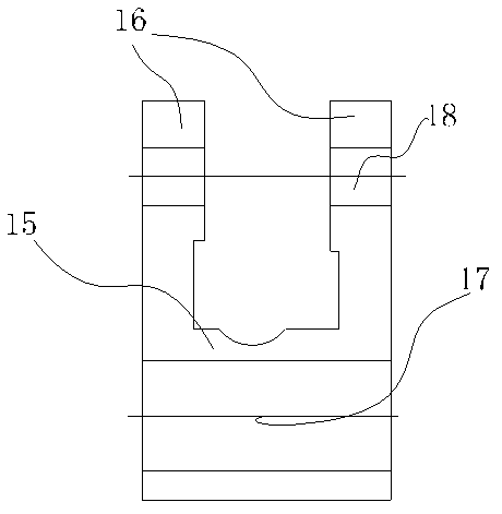
[0018] figure 1 Shown is the schematic cross-sectional view of the front view of the connecting rod. The connecting rod has a connecting seat 15 and a pair of connecting arms 16 oppositely arranged at both ends of the top of the connecting seat 15. Connected first through hole 17, second through hole 18.

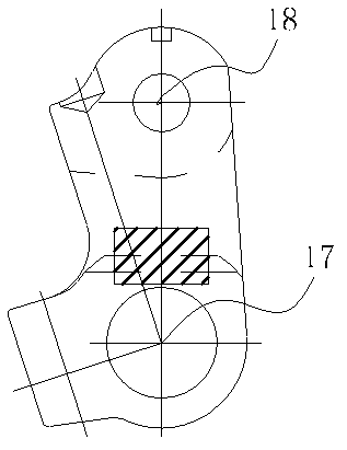
[0019] figure 2 A schematic side view of the connecting rod is shown. During injection molding, the first through hole 17 and the second through hole 18 are formed along the vertical direction.

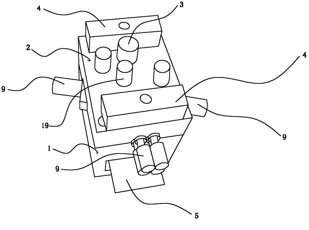
[0020] image 3 It shows that a movable mold 2 is covere...


PUM


Abstract

The invention provides an injection mould for a connecting rod. The injection mould comprises a fixed mold, a mold core in the fixed mold, and a movable mold which can be pressed on the fixed mold; a horizontal through hole is formed at the lower part of the fixed mold; a mold picking plate is arranged in the horizontal through hole along a horizontal direction; parting surfaces are formed on the combined part of the fixed mold and the movable mold; a first cavity is formed between the fixed mold and the mold core; a sliding chute is formed on the parting surface of the movable mold; a drawing block is arranged and can be slipped into the sliding chute; a second cavity is formed at the bottom part of the sliding chute; the first cavity and the second cavity can be closed to each other to form a complete cavity; pouring channels are formed and are used for communicating the first cavity and the second cavity with the outside; a hole channel is formed and can pass through the movable mold and then is inserted into the top part of the mold core; a drawing pin is arranged and can be inserted into the hole channel; and the bottom part of the mold core is connected with the mold picking plate. By adopting the injection mould for the connecting rod, the production efficiency of an enterprise is improved to a certain extent, the cost of the enterprise is saved, and the demand on processing of the connecting rod can be met better.

Description

technical field [0001] The invention relates to an injection mold, in particular to an injection mold with double-layer cavities which is specially used for producing connecting rods. Background technique [0002] In some current injection molds dedicated to processing connecting rods, there are still some shortcomings in the design of the mold base, especially the cavity, runner and mold taking device in the mold base. In terms of cavity design, although it is possible to design a better cavity according to the shape of the connecting rod to be processed, in some small aspects such as some connecting rods, it is usually necessary to open some holes and especially like Some complex shapes of the connecting rod involved in the present invention usually cannot be completed in one pouring in the cavity, but need to be processed through other steps after molding, and the operation is very troublesome; and in terms of runner design, Due to some unreasonable gate designs usually ...

Claims


Application Information

Patent Timeline
Patent Type & Authority Patents(China)
IPC IPC(8): B29C45/32B29C45/27B29C45/40
Inventor 孙林军
Owner SUZHOU LASERHOWER PRECISION CASTING
Why Eureka
Try Eureka