Bone spicule structure

A bone needle and needle-based technology, which is applied in the field of medical clinical internal surgical instruments, can solve the problems of losing the fixation effect of the bone needle and the separation of fractured bones.

Inactive Publication Date: 2016-06-08
无锡市闻泰百得医疗器械有限公司
View PDF3 Cites 0 Cited by
  • Summary
  • Abstract
  • Description
  • Claims
  • Application Information

AI Technical Summary

Problems solved by technology

[0002] In clinical medical operations, fractures are usually treated with bone spicules combined with bone plates. In order to reduce the penetration resistance of bone spicules, the existing bone spicules have a smooth surface structure. When fixing the fractured bone body, the bone body will slide relative to the spicule, thus causing the separation of the fractured bone body and losing the fixation effect of the spicule

Method used


Image

  • Bone spicule structure

Examples


Embodiment Construction

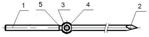
[0008] See figure 1 , a bone spicule structure, which includes a bone spicule body 1 , a first through hole 2 is arranged in the bone spicule body 1 , and a second through hole 3 intersecting with the first through hole 2 is set on the bone spicule body 1 .

[0009] The bone needle body 1 is provided with a collar 4 , and the second through hole 3 is arranged in the collar 4 , which ensures the processing of the collar 4 , thereby ensuring the processing of the second through hole 3 .

[0010] A groove 5 is provided on the side of the collar 3, and the steel wire or cable is wound on the groove 5, which prevents the steel wire or cable from slipping and further ensures the stable fixation of the bone needle and the bone body.

[0011] The first through hole 2 is perpendicular to the second through hole 3, which further reduces the processing difficulty of the second through hole.


PUM


Abstract

The invention provides a bone spicule structure, effectively preventing sliding of a bone plate relative to a bone spicule, and ensuring joint effect of fracture bone bodies. The bone spicule structure comprises a bone spicule body. The bone spicule body is internally provided with a first hole. The bone spicule structure is characterized in that the bone spicule body is provided with a second hole intersecting the first hole.

Description

technical field [0001] The invention relates to the technical field of internal medical surgical instruments, in particular to a bone needle structure. Background technique [0002] In clinical medical operations, fractures are usually treated with bone spicules combined with bone plates. In order to reduce the penetration resistance of bone spicules, the existing bone spicules have a smooth surface structure. When fixing the fractured bone body, the bone body will slide relative to the spicule, thus causing the separation of the fractured bone body and losing the fixation effect of the spicule. Contents of the invention [0003] In view of the above problems, the present invention provides a bone spicule structure, which effectively prevents the relative sliding of the bone plate relative to the bone spicule, and ensures the joint effect of the fractured bone body. [0004] Its technical solution is as follows: a bone needle structure, which includes a bone needle body, ...

Claims


Application Information

Patent Timeline
Patent Type & Authority Applications(China)
IPC IPC(8): A61B17/84A61B17/66
Inventor 宋普庆赵淮张忠祥邱文宾裴云霜
Owner 无锡市闻泰百得医疗器械有限公司
Why Eureka
Try Eureka