Precise pneumatic clamping mechanical gripper for thin plate type workpiece

A technology of manipulator claw and pneumatic clamp, used in manipulator, metal processing mechanical parts, clamping and other directions, can solve the problem of difficulty in ensuring workpiece positioning accuracy requirements, and achieve the effect of high repeated positioning accuracy

Active Publication Date: 2016-06-08
黄山市开发投资集团有限公司
View PDF7 Cites 9 Cited by
  • Summary
  • Abstract
  • Description
  • Claims
  • Application Information

AI Technical Summary

Problems solved by technology

[0002] In the field of mechanical engineering, grippers are commonly used in the clamping scheme of thin-plate workpieces, such as various pneumatic grippers, with a general accuracy of 0.03 to 0.05mm. On the production line higher tha

Method used


Image

  • Precise pneumatic clamping mechanical gripper for thin plate type workpiece
  • Precise pneumatic clamping mechanical gripper for thin plate type workpiece
  • Precise pneumatic clamping mechanical gripper for thin plate type workpiece

Examples


Embodiment Construction

[0038] Below in conjunction with accompanying drawing, the present invention will be further described through embodiment.

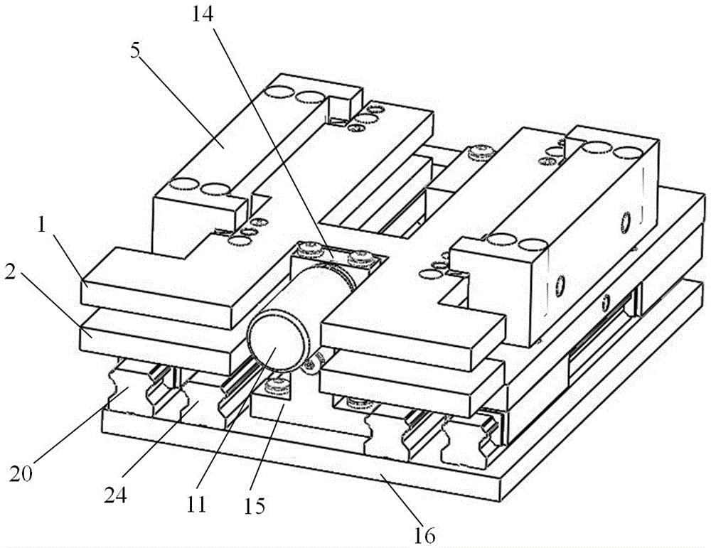
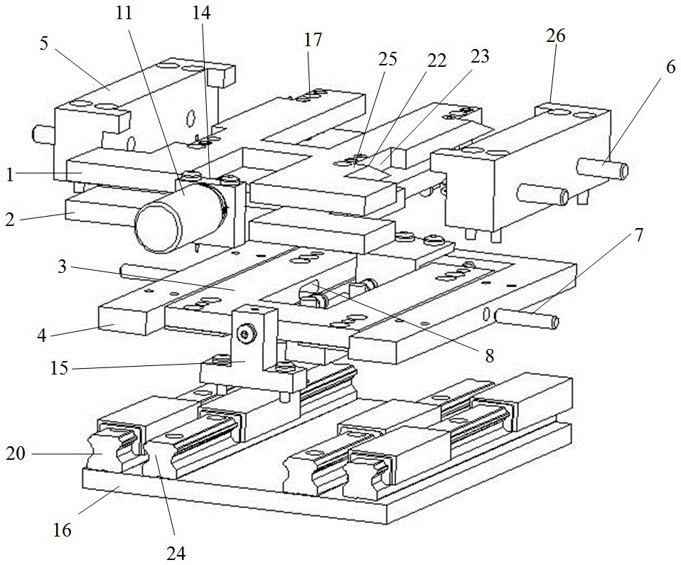
[0039] see figure 1 , a precision pneumatic clamping mechanical gripper for thin plate workpieces includes a gripping mechanism, a gripper moving mechanism and a template moving mechanism.

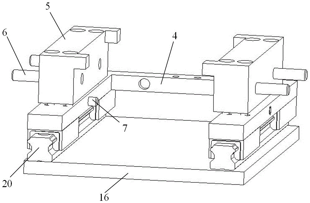
[0040] see figure 2 , The claw clamping mechanism includes a pair of plate-shaped claws corresponding up and down, a pair of formers and a positioning mechanism corresponding to left and right. The claw moving mechanism includes a sliding base plate 3 and a pair of inner guide rails 24 . The former moving mechanism includes a U-shaped frame 4, a cylinder 10 and a pair of outer guide rails 20.

[0041] A pair of plate-shaped claws includes an upper splint 1 and a lower splint 2 corresponding up and down. Both the upper splint 1 and the lower splint 2 are H-shaped plates, and one end in the length direction is a clamping end.

[0042] The bottom of the lower splin...


PUM


Abstract

The invention relates to a precise pneumatic clamping mechanical gripper for a thin plate type workpiece. The precise pneumatic clamping mechanical gripper comprises a gripper clamping mechanism, a gripper moving mechanism and an explorator moving mechanism, wherein the gripper clamping mechanism comprises a pair of plate-shaped claws in up-down correspondence, a pair of explorators in left-right correspondence and a positioning mechanism; the gripper moving mechanism comprises a sliding bottom plate and a pair of inner guide tracks; the explorator moving mechanism comprises a U-shaped frame, an air cylinder and a pair of outer guide tracks; the air cylinder is used for driving the pair of explorators to move in a reciprocating manner through the U-shaped frame, and used for controlling the pair of plate-shaped claws to clamp and release in the movement process; meanwhile the pair of claws is moved in a reciprocating manner along the pair of inner guide tracks through the sliding bottom plate. The precise pneumatic clamping mechanical gripper is reasonable in structural design, and all types of action such as overall movement of the mechanical gripper and clamping and release of upper and lower clamping plates of the mechanical gripper can be achieved through the one air cylinder.

Description

technical field [0001] The invention relates to the field of precision machinery, and relates to a pneumatic clamping device. Background technique [0002] In the field of mechanical engineering, grippers are commonly used in the clamping scheme of thin-plate workpieces, such as various pneumatic grippers, with a general accuracy of 0.03 to 0.05mm. On the production line higher than 0.01mm, it is difficult to ensure the positioning accuracy requirements of the workpiece only by using ordinary pneumatic grippers to clamp the workpiece, which often requires a more complicated positioning and clamping mechanism to complete. Contents of the invention [0003] The purpose of the present invention is to provide a pneumatic clamping gripper with high repeat positioning accuracy, compact structure, high efficiency and quickness, so as to meet the requirements of high-precision and fast clamping of thin plate workpieces, and the precision can reach 0.01 to 0.02mm. [0004] A preci...

Claims


Application Information

Patent Timeline
IPC IPC(8): B23Q3/08B25J15/06
CPCB23Q3/065B23Q3/08B25J15/06
Inventor 黄斌易嘉靖陶佳月李鹏涛陆双双郝最杨广文
Owner 黄山市开发投资集团有限公司
Why Eureka
Try Eureka