
Split parachute ejection pod for drones

A separate, unmanned aerial vehicle technology, applied in the direction of parachutes, aircraft parts, aircraft landers, etc., can solve problems such as parachute failure, main parachute entanglement, parachute and fuselage structure entanglement, etc., to achieve reliable work, avoid entanglement, The effect of simple and compact structure

Active Publication Date: 2017-10-20
CHANGGUANG SATELLITE TECH CO LTD
View PDF2 Cites 0 Cited by
  • Summary
  • Abstract
  • Description
  • Claims
  • Application Information

AI Technical Summary

Problems solved by technology

[0003] In order to solve the existing UAV parachute problems such as the entanglement between the parachute and the fuselage structure, the failure of the parachute to open the parachute in time, and the entanglement between the fuselage and the lead parachute and the main parachute, the present invention provides a Detachable parachute ejection bay for drones

Method used


Image

  • Split parachute ejection pod for drones
  • Split parachute ejection pod for drones
  • Split parachute ejection pod for drones

Examples


specific Embodiment approach 1

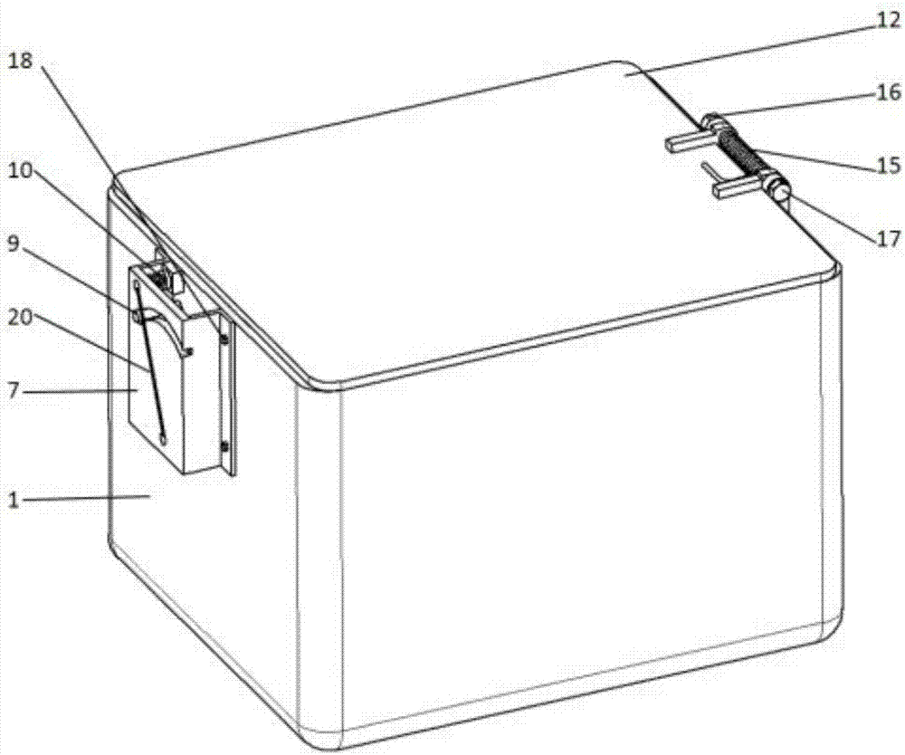
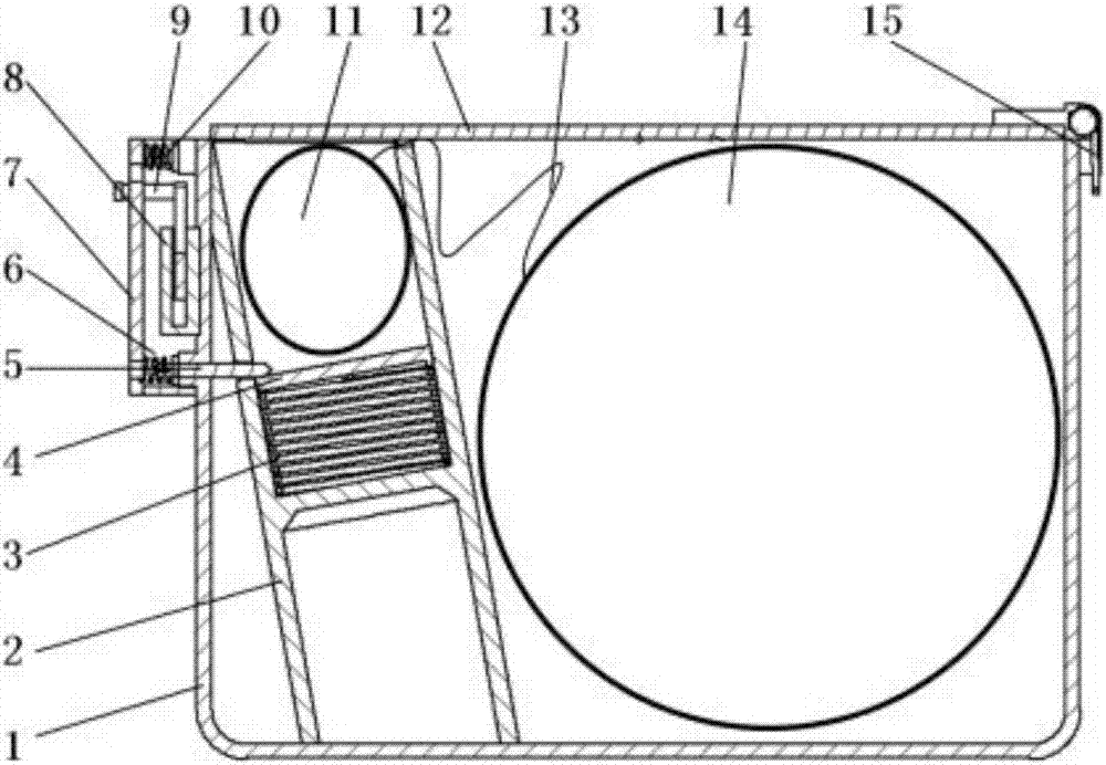
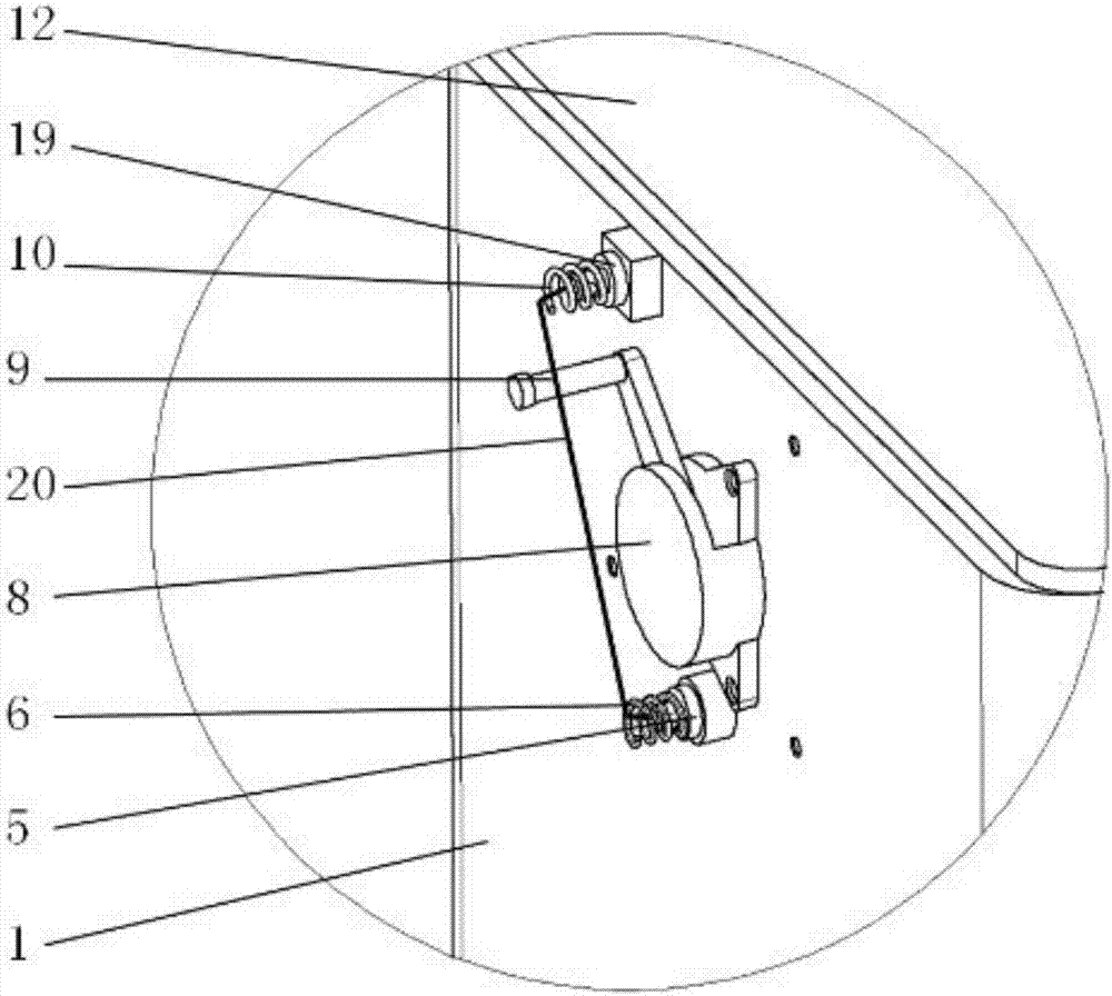
[0021] Specific implementation mode 1. Combination Figure 1 to Figure 9 Illustrate this embodiment, the detachable parachute ejection cabin that is used for unmanned aerial vehicle, comprises main umbrella cabin 1, main umbrella 14, pilot parachute cabin 2, pilot parachute 11, umbrella cabin cover 12, umbrella rope 13, ejection spring 3, Ejection plate 4, unlocking mechanism and connecting mechanism. The parachute compartment 2 is obliquely arranged inside the main parachute compartment 1, and the bottom of the parachute compartment 2 is bonded inside the main parachute compartment 1 with resin glue and glass cloth; The plate 4 presses the ejection spring 3 into the parachute cabin 2, and locks it through the ejection lock cylinder 5 of the unlocking mechanism; the parachute 11 and the main parachute 14 are connected by an inter-umbrella rope 13, and the parachute is stacked into a cylindrical plug Enter the parachute compartment 2, press the ejection plate 4, and put the ma...

specific Embodiment approach 2

[0027] Embodiment 2. This embodiment is the assembly process of the separate parachute ejection chamber for unmanned aerial vehicles described in Embodiment 1: it is realized by the following steps:

[0028] Step 1. Match the bottom surface of the parachute compartment 2 with the bottom surface and the side of the main parachute compartment 1, and ensure that the ejection lock cylinder 5 can pass through the two smoothly. Use resin glue and glass cloth to connect the parachute compartment 2 and the main parachute compartment. 1 Glue firmly on the bottom.

[0029] Step 2: Put the ejection spring 3 and the ejection plate 4 into the parachute compartment 2 in turn, compress the ejection spring 3 with the ejection plate 4, and use the ejection lock cylinder 5 to pass through the parachute compartment 2 and the main parachute compartment 1 to clamp the ejection spring 3 and ejection plate 4.

[0030] Step 3, fold the main parachute 14 and put it into the main parachute compartment...


PUM


Abstract

The invention discloses a separated type parachute ejection capsule for an unmanned aerial vehicle, relating to the technical field of parachuting recovery for the unmanned aerial vehicle and aiming at solving the problems of the existing parachute for the unmanned aerial vehicle that a parachute and a vehicle body structure are intertwined, and the parachute is ejected out and opened untimely to cause parachuting failure and the intertwining phenomenon of the vehicle body with a parachute cover and a main parachute. The separated type parachute ejection capsule for the unmanned aerial vehicle comprises a main parachute capsule, a parachute cover capsule, a parachute capsule cover, an ejection spring, an ejection plate, an unlocking mechanism and a connecting mechanism, wherein the parachute cover capsule is obliquely arranged inside the main parachute capsule, and the parachute capsule cover is movably connected with the main parachute capsule by the connecting mechanism; the ejection plate tightly presses the ejection spring into the parachute cover capsule and is locked by an ejection lock cylinder of the unlocking mechanism; and when the parachute cover is ejected out of the capsule and is expanded by the unlocking mechanism, the main parachute can be drawn to be out of the capsule. According to the separated type parachute ejection capsule, the parachute cover capsule is obliquely arranged towards the head part of the vehicle rather than upward installation perpendicular to the vehicle body, so that components of the heading ejection speed are utilized to counteract the backwards-movement trend of the parachute cover influenced by airflows, and the intertwining phenomenon of the vehicle body and the parachute cover is avoided; and the separated type parachute ejection capsule has a simple and compact structure.

Description

technical field [0001] The invention relates to the technical field of parachute recovery of unmanned aerial vehicles, in particular to a separate parachute ejection chamber of an unmanned aerial vehicle. Background technique [0002] At present, parachuting is the main way to recover UAVs. The main function of parachutes is to protect UAVs during the recovery process and prevent damage during landing. At present, the reliability of parachute opening is an important problem for parachute landing. The parachute is entangled with the fuselage structure, and the parachute is out of the cabin and the parachute is not opened in time, which will lead to parachute failure. The emergency parachute drop device proposed by Chinese patent CN103895870A uses the parachute spring to open the cabin and throws the parachute vertically upwards to the body. The parachute throwing is relatively reliable, but the throwing direction is upward, which cannot offset the trend of the airflow forcing...

Claims


Application Information

Patent Timeline
Patent Type & Authority Patents(China)
IPC IPC(8): B64D45/04B64D17/80
CPCB64D17/80B64D45/04
Inventor 薛志鹏王雷贾宏光厉明宋洋王鹏鹏
Owner CHANGGUANG SATELLITE TECH CO LTD
Learn More