
Nephelometric turbidimeter vial arrangement

A turbidity meter, scattering technology, applied in the field of scattering turbidity meter bottle device, can solve the problem that it is difficult to determine the intensity of the main light signal

Active Publication Date: 2016-06-08
HACH LANGE HACH LANGE
View PDF4 Cites 2 Cited by
  • Summary
  • Abstract
  • Description
  • Claims
  • Application Information

AI Technical Summary

Problems solved by technology

A secondary signal with high intensity would make it difficult, if not impossible, to determine the intensity of the primary light signal

Method used


Image

  • Nephelometric turbidimeter vial arrangement
  • Nephelometric turbidimeter vial arrangement
  • Nephelometric turbidimeter vial arrangement

Examples


Embodiment Construction

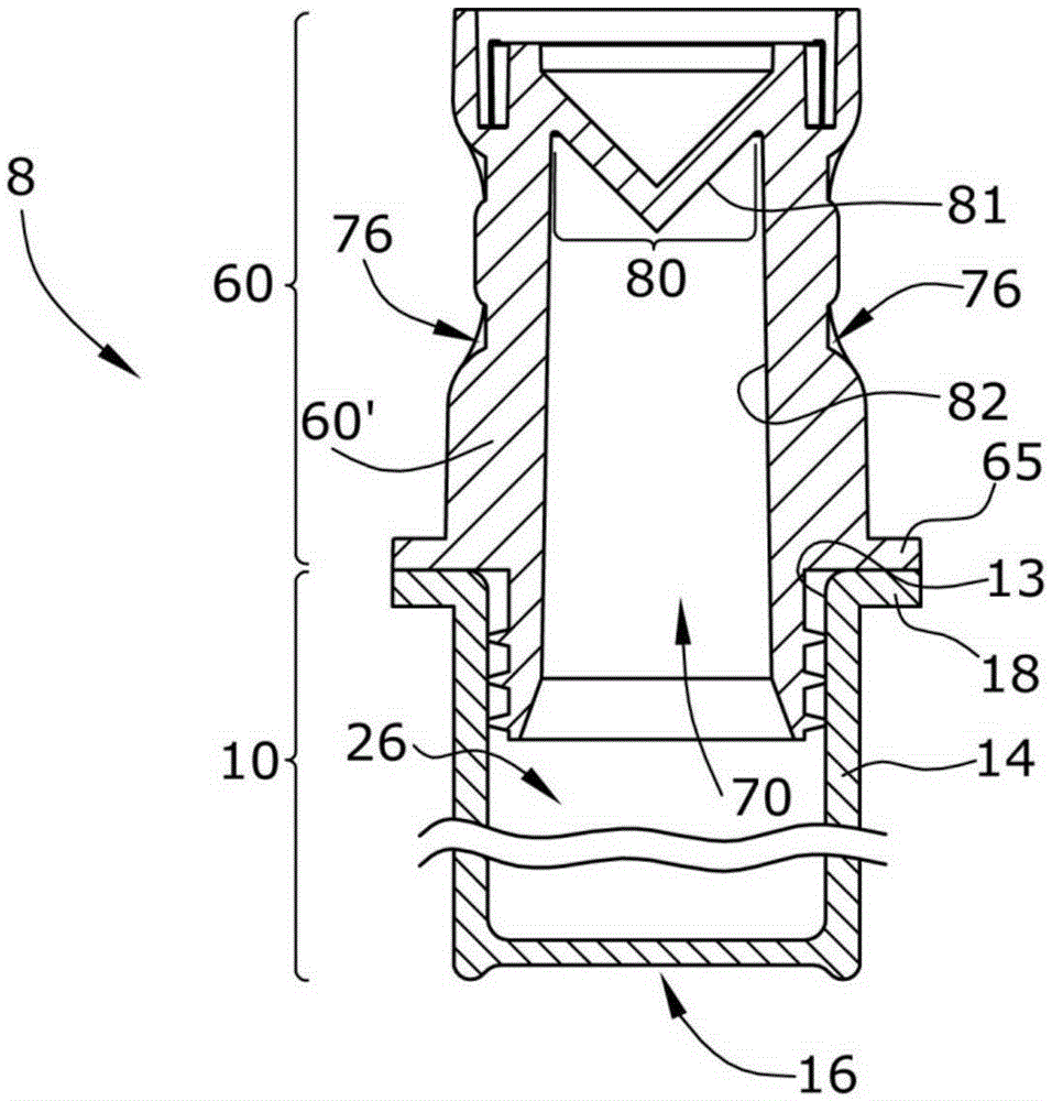
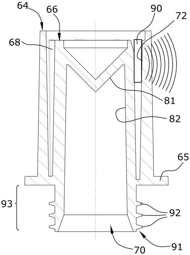
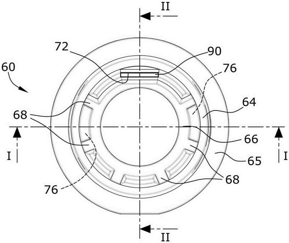
[0027] Figures 1 to 8 Two embodiments of a bottle device 8; 8' are shown in . Figures 1 to 4 The bottle device 8 of the first embodiment shown in has a ratio Figures 5 to 8 The optical trap of the vial device 8' shown in the second embodiment is a more complex optical trap. Both bottle devices 8; 8' have a substantially cylindrical and can-like bottle 10 with a top bottle opening 13 closed by a separate bottle cap 60; 61. The bottle body 14 is made of transparent glass. The individual caps 60; 61 are made of opaque and black plastic.

[0028] Both bottle devices 8; 8' are suitable for use in nephelometers having a measurement light source generating a measurement beam passing through the transparent bottom light entrance window of the bottle 10 16 is guided axially into the bottle interior. The light source generates measurement light with a suitable wavelength, and the light entrance window 16 is transparent for the measurement light. At the top end of the bottl...


PUM


Abstract

A nephelometric turbidimeter vial arrangement includes a vial and a separate vial cap. The vial comprises a transparent cylindrical vial body configured to enclose a vial interior, a bottom inlet window, and a top vial opening configured to be circular. The separate vial cap comprises a light trap cavity. The separate vial cap is configured to close the top vial opening. The light trap cavity comprises an inner surface which comprises a light absorbing surface. The light trap cavity is configured to be open to the vial interior.

Description

technical field [0001] The present invention relates to nephelometer bottle assemblies for use in nephelometers. Background technique [0002] Nephelometers determine the concentration of solid particles or other particles suspended in a fluid, which can typically be a liquid, a gas, or a gas-liquid mixture. US8724107B2 discloses a nephelometer having a cylindrical nephelometer bottle comprising an optically transparent and flat bottom inlet window through which a measuring beam passes axially into the bottle interior. The cylindrical portion of the cylindrical body of the bottle defines a transparent exit window through which light scattered by the suspended particles radially exits the interior of the bottle and is received by the light detection means. The received primary light signal, which is produced only by light scattered within the relevant fluid volume, has a lower intensity. Therefore, any light that is not produced by light scattered within the relevant fluid ...

Claims


Application Information

Patent Timeline
Patent Type & Authority Applications(China)
IPC IPC(8): B65D23/00B65D51/24G01N21/51
CPCG01N21/51G01N2021/513G01N2201/0642G01N21/15G01N2201/0227
Inventor 曼弗雷德·巴特费尔德巴斯·德·海伊汉斯-乔基姆·孔普赫安德里亚斯·米特赖特安德里亚斯·格尔利茨
Owner HACH LANGE HACH LANGE
Learn More