Flanged joint bearing installation device

A joint bearing and installation device technology, which is applied to bearing components, shafts and bearings, mechanical equipment, etc., can solve problems such as insufficient bearing flange compression, joint bearing loosening and falling off, joint bearing stagnation, etc.

Pending Publication Date: 2016-06-08
HARBIN DONGAN ENGINE GRP
View PDF0 Cites 4 Cited by
  • Summary
  • Abstract
  • Description
  • Claims
  • Application Information

AI Technical Summary

Problems solved by technology

In the existing installation method, after the bearing is pressed into the bearing seat by a pressing tool, the outer ring of the bearing is deformed by an external force and then turned outwards, and then stuck on the chamfer set on the edge of the bearing seat to realize the pressing function; However, this method does not take into account the amount of flanging of

Method used


Image

  • Flanged joint bearing installation device
  • Flanged joint bearing installation device
  • Flanged joint bearing installation device

Examples


Embodiment Construction

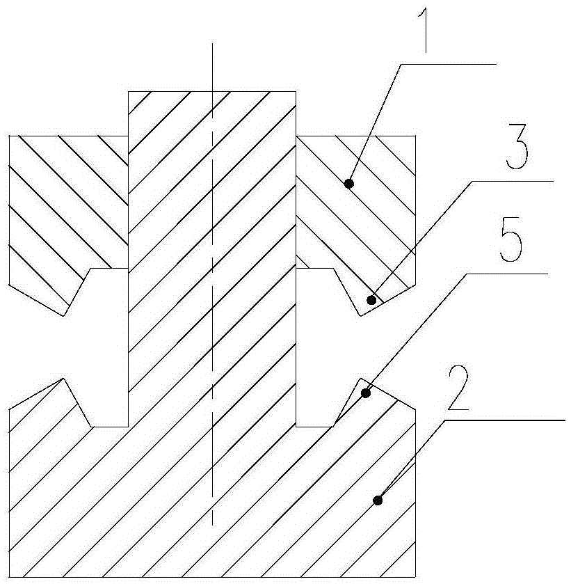
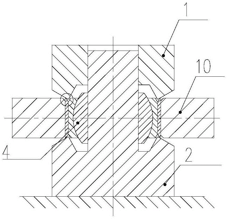
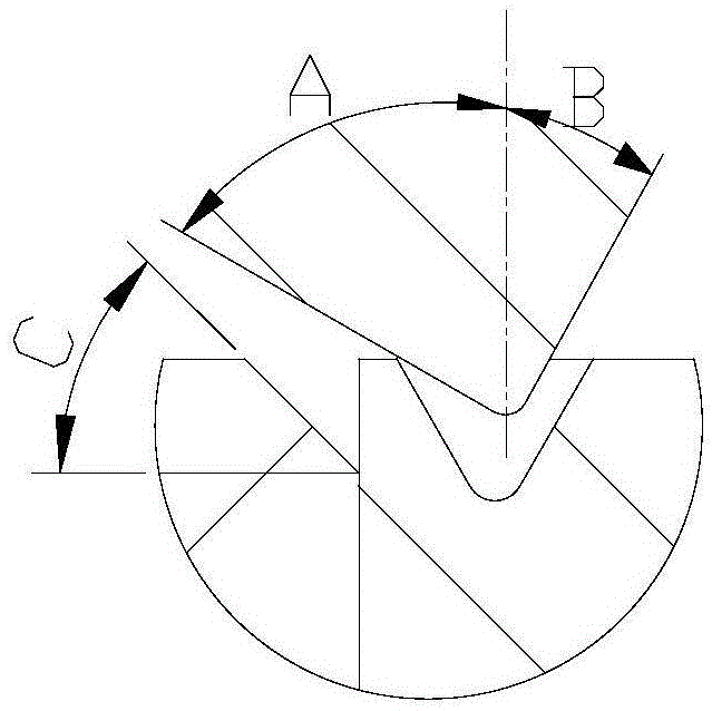
[0009] As shown in the figure, the installation device of the flanged joint bearing includes a pressure head 1 and a guide sleeve shaft 2. The pressure head 1 is a hollow structure, and a positioning shaft is arranged on the guide sleeve 2. The pressure head 1 is connected with the guide sleeve 2 through the center hole. The positioning shaft on the top is clearance fit, and the pressure head can move on the positioning shaft. The upper end of the pressure head 1 is a plane, which is used for pressing the press; the lower end is provided with a V-shaped ring-shaped tip 3 with the tip pointing downward. The angle of the V-shaped annular tip 3 is A+B, where A is the angle between the outer surface of the V-shaped annular tip 3 and the vertical direction, and the angle should satisfy C


PUM

PropertyMeasurementUnit
Diameteraaaaaaaaaa
Chamferaaaaaaaaaa

Abstract

The invention relates to a flanged joint bearing installation device which comprises a pressing head and a guide shaft sleeve. The pressing head is of a hollow structure, a positioning shaft is arranged on the guide shaft sleeve, and the pressing head is in clearance fit with the positioning shaft on the guide shaft sleeve through a center hole. The upper end of the pressing head is a plane, and the lower end of the pressing head is provided with a V-shaped annular pointed end with a downward pointed end body. The diameter of the V-shaped annular pointed end is not smaller than that of a V-shaped annular groove on the outer circle of a joint bearing. A base of the guide shaft sleeve is provided with a V-shaped annular pointed end which is identical with the V-shaped annular pointed end, with the downward pointed end body, on the pressing head in size and symmetric with the V-shaped annular pointed end, with the downward pointed end body, on the pressing head in position. The flanged joint bearing installation device overcomes the difficulty that the joint bearing is likely to deviate and stagger in the flanging process, and solves the problem that flanging amount is not enough, accordingly pressing of the joint bearing is not sufficient and the bearing falls off.

Description

technical field [0001] The invention relates to a joint bearing installation device, which is especially suitable for the installation of the joint bearing whose outer ring needs flanging. Background technique [0002] The main function of the joint bearing is spherical transmission. During use, it can rotate, swing, and tilt around the axis to improve the stability of the connecting parts. It has the functions of self-aligning, high load, and maintenance-free. The quality of joint bearing installation directly affects the service life and safety of the entire system. For the joint bearing whose outer ring needs to be flanged, in addition to assembling it to the bearing mounting seat according to the requirements of the bearing, it also involves the compression of the flanging. In the existing installation method, after the bearing is pressed into the bearing seat by a pressing tool, the outer ring of the bearing is deformed by an external force and then turned outwards, an...

Claims


Application Information

Patent Timeline
IPC IPC(8): F16C43/00
CPCF16C43/00
Inventor 徐童童欧阳可平冯磊于伟周丽芳李远徐秀波胡克伟齐晓辉张羽
Owner HARBIN DONGAN ENGINE GRP
Why Eureka
Try Eureka