
Torsion damper

A torsional vibration and shock absorber technology, which is applied in the direction of spring/shock absorber, vibration suppression adjustment, mechanical equipment, etc., can solve the problems of poor vibration damping characteristics, staggered centrifugal counterweights, etc., and achieve improved effects and improved vibration reduction effect, the effect of increasing the effective pendulum mass

Active Publication Date: 2016-06-08
SCHAEFFLER TECH AG & CO KG
View PDF5 Cites 2 Cited by
  • Summary
  • Abstract
  • Description
  • Claims
  • Application Information

AI Technical Summary

Problems solved by technology

The pendulum masses are riveted to one another via spacer elements, as a result of which an offset of the centrifugal weights can occur, which can lead to poor damping properties

Method used


Image

  • Torsion damper
  • Torsion damper
  • Torsion damper

Examples


Embodiment Construction

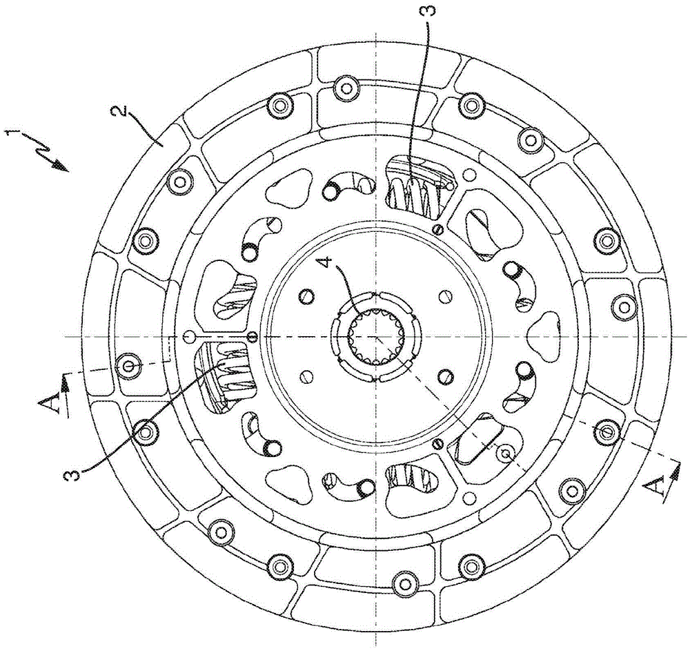
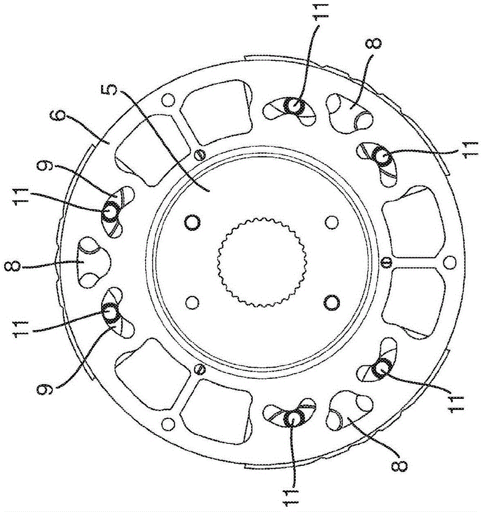
[0029] figure 1 The torsional vibration damper 1 is shown in side view, figure 2 The torsional vibration damper 1 is shown in section. Torsional vibration damper 1 in figure 1 and 2 The embodiment is shown as a clutch disc.

[0030] A radially outer friction lining is used as the input element 2 of the torsional vibration damper 1 , which friction lining is able to resist the restoring force of at least one force accumulator 3 against the output element 4 , in particular a hub such as a clutch disc. rotate. In this case, two spaced-apart disks are connected to the input element 2 , said two disks having windows in which the force accumulator 3 is arranged. A flange is inserted between the two discs, which flange is connected to the hub 4 and also has a window in which the force accumulator 3 is inserted. The twisting between the input element 2 and the output element 4 against the restoring force of the force store 3 takes place due to the twisting between the disk and ...


PUM


Abstract

The invention relates to torsion damper (1) comprising an input element (2) and an output element (4), wherein the input element can turn relative to the output element against the force applied by at least one energy accumulator (3), wherein connected to the input element or the output element there is a support (5) composed of two joined support discs, wherein between the two support discs at least one pendulum mass (8) can be moved relative to the support discs.

Description

technical field [0001] The invention relates to a torsional vibration damper, in particular for a drive train of a motor vehicle. Background technique [0002] In motor vehicles, torsional vibration dampers are arranged in the drive train to dampen torque inhomogeneities caused by the combustion process. In this context, torsional vibration dampers are known with a centrifugal pendulum, wherein the centrifugal pendulum is fastened via a disc to the hub of the clutch disc and is displaceable on rails in the disc on both sides of the disc as carrier Arranged in such a way that there is a centrifugal weight as a pendulum mass. In this case, the pendulum mass is arranged in such a way that it has a predetermined distance from the disk, thereby ensuring free displaceability of the pendulum mass for optimal vibration damping. However, this is disadvantageous with regard to the required installation space, since this requires additional installation space which is then no longer ...

Claims


Application Information

Patent Timeline
IPC IPC(8): F16F15/129
CPCF16F15/129F16F15/1238F16F15/145
Inventor A·鲁施
Owner SCHAEFFLER TECH AG & CO KG
Learn More