
Vibrator loudspeaker and implementation method thereof

An implementation method and speaker technology, applied in the field of vibrator speakers, can solve the problems of limited height compression space, cumbersome production process, low production cost, etc., and achieve the effects of more linear vibration, reduced production process, and saved height space.

Pending Publication Date: 2020-11-24
ZHEJIANG ANYALL AUDIO TECH CO LTD
View PDF0 Cites 0 Cited by
  • Summary
  • Abstract
  • Description
  • Claims
  • Application Information

AI Technical Summary

Problems solved by technology

Traditional loudspeakers include structures such as dust covers, sound cones, and basin frames. The manufacturing process is cumbersome, and the highly compressed space is limited. Currently, the thickness of the products is more than 20mm.
[0003] With the development of science and technology, people's pursuit of quality of life is getting higher and higher. Traditional speakers can no longer meet the needs of the market. Therefore, there is an urgent need for a speaker with a thickness of less than 10mm, and it needs to have fewer production processes. Features of low production cost

Method used


Image

  • Vibrator loudspeaker and implementation method thereof
  • Vibrator loudspeaker and implementation method thereof
  • Vibrator loudspeaker and implementation method thereof

Examples


Embodiment 1

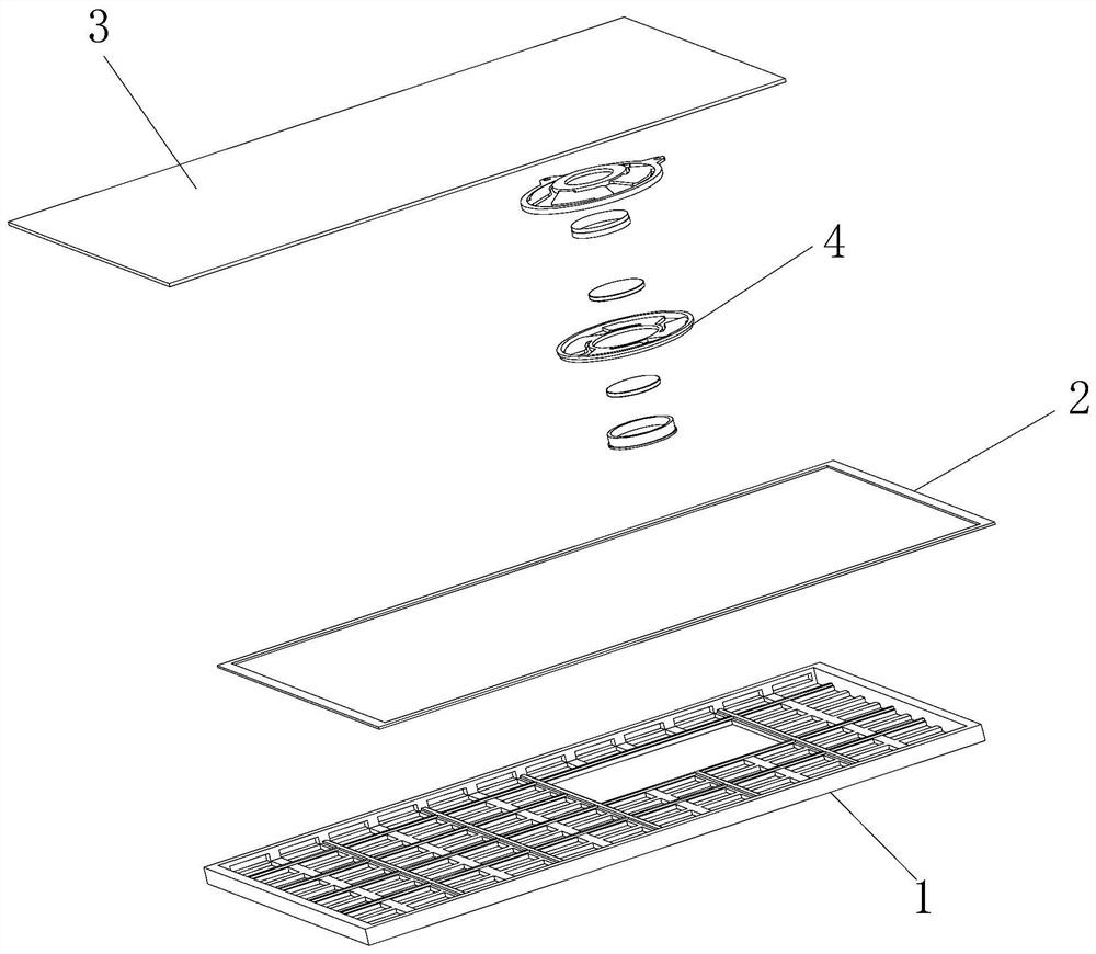
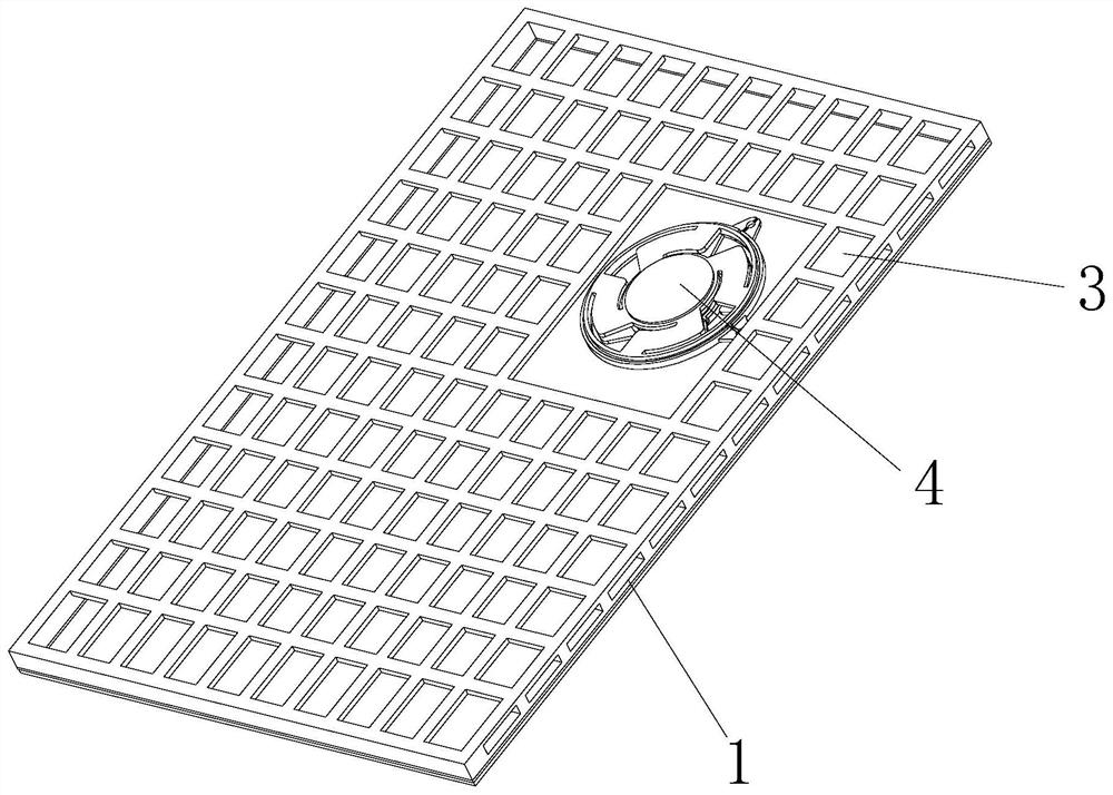
[0031] see Figure 1-5 , the present invention provides the following technical solutions: a vibrator speaker, including a bracket 1, a honeycomb panel 3 is arranged above the bracket 1, a speaker body 4 is connected to the honeycomb panel 3, and the speaker body 4 is located between the bracket 1 and the honeycomb panel 3, Loudspeaker body 4 comprises upper cover 41, voice coil 42, lower cover 43, magnetic steel 45 and U iron 46, wherein, upper cover 41 is connected with honeycomb panel 3, voice coil 42 is embedded in the inside of upper cover 41, lower cover 43 and The upper cover 41 is connected, the inside of the lower cover 43 is connected with a U-iron 46, the magnetic steel 45 is embedded in the inside of the U-iron 46, and the support 1 and the honeycomb panel 3 are rectangular structures.

[0032] Further, an upper splint 44 is connected above the magnetic steel 45 .

[0033] By adopting the above technical solution, the upper splint 44 conducts magnetic conduction, ...

Embodiment 2

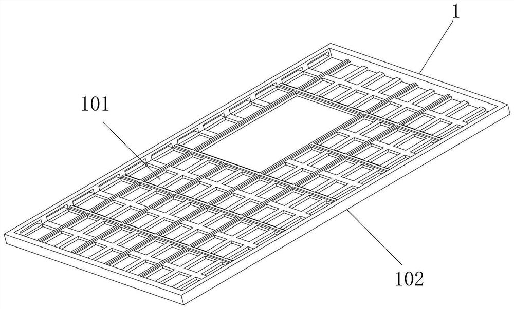
[0039] The difference between this embodiment and Embodiment 1 lies in: further, several rectangular grooves 101 are uniformly provided inside the bracket 1 .

[0040] By adopting the above technical solution, the rectangular groove 101 can reduce the blocking of sound waves and increase the rigidity of the bracket 1 .

[0041] Further, the implementation method of the vibrator speaker described in the present invention includes the following steps:

[0042] (1), the voice coil 42 is bonded to the inside of the loam cake 41;

[0043] (2), upper splint 44 and magnetic steel 45 are bonded together, and are bonded in the inside of U iron 46, and U iron 46 injection molding is connected in the inside of lower cover 43;

[0044] (3), the upper cover 41 and the lower cover 43 are buckled and connected, and the upper cover 41 is fixed on the honeycomb panel 3;

[0045] (4), the shock-absorbing cotton 2 is bonded on the flange 102 of the support 1, and the honeycomb panel 3 is bonde...


PUM


Abstract

The invention discloses a vibrator loudspeaker comprising a bracket. As honeycomb plate is arranged above the bracket; the honeycomb plate is connected with a loudspeaker body, the loudspeaker body islocated between the bracket and the honeycomb plate; the loudspeaker body comprises an upper cover, a voice coil, a lower cover, magnetic steel and U-shaped iron, the upper cover is connected with the honeycomb plate, the voice coil is embedded into the upper cover, the lower cover is connected with the upper cover, the U-shaped iron is connected into the lower cover, and the magnetic steel is embedded into the U-shaped iron. The invention further discloses an implementation method of the vibrator loudspeaker. The voice coil is arranged on the upper cover, the magnetic circuit formed by the upper clamping plate, the magnetic steel and the U-shaped iron is arranged on the lower cover, the upper cover and the lower cover are combined, a traditional loudspeaker voice coil positioning mode isomitted, production procedures are reduced, so that production cost is reduced.

Description

technical field [0001] The invention belongs to the technical field of vibrator loudspeakers, and in particular relates to a vibrator loudspeaker and a realization method thereof. Background technique [0002] The working principle of the traditional loudspeaker is that the energized coil is stressed in the magnetic field, the voice coil generates axial reciprocating motion, drives the sound cone connected to the voice coil to vibrate, compresses the air, and generates sound wave radiation. Traditional loudspeakers include structures such as dust covers, sound cones, and basin frames. The manufacturing process is cumbersome, and the space for high compression is limited. Currently, the thickness of the products is more than 20mm. [0003] With the development of science and technology, people's pursuit of quality of life is getting higher and higher. Traditional speakers can no longer meet the needs of the market. Therefore, there is an urgent need for a speaker with a thick...

Claims


Application Information

Patent Timeline
Patent Type & Authority Applications(China)
IPC IPC(8): H04R9/06H04R9/04H04R9/02
CPCH04R9/02H04R9/045H04R9/06
Inventor 葛君波胡朝华薛峰金婵瑜
Owner ZHEJIANG ANYALL AUDIO TECH CO LTD
Learn More