
Novel button

A button, a new type of technology, applied in the direction of fasteners, press fasteners, press fasteners, etc., can solve the problems of insufficient fastening force, no support part, easy to fall off, etc., to achieve compact structure design, stable positioning, and fit good sex effect

Active Publication Date: 2016-06-15
SHISHI LONGXIANG HARDWARE PLASTIC PROD CO LTD
View PDF4 Cites 2 Cited by
  • Summary
  • Abstract
  • Description
  • Claims
  • Application Information

AI Technical Summary

Problems solved by technology

[0003] At present, in the structural design of the four-button button, the focus is only on the connection performance between the two sets of buttons (that is, between the male button and the female button), but no consideration is given to the connection performance between the two parts of the female button and the male button. Too much attention is paid to the fact that the two parts are held together by a cracked and folded buckle foot to achieve mutual fixation. However, the cracked and folded buckle foot is exposed and there is no relevant supporting part for covering and positioning. There are problems such as instability, poor durability, and easy to fall off after a certain period of time, that is, the problem of button damage often occurs due to the insufficient stability and firmness of the fastening force between the two parts of the female button or the male button.
In addition, the compactness and stability of the structural assembly of the button itself, as well as the fit with the clothing, also need to be considered, and the current button design still has defects in this aspect

Method used


Image

  • Novel button
  • Novel button
  • Novel button

Examples


Embodiment Construction

[0027] The present case will be described in further detail below in conjunction with the accompanying drawings and specific embodiments.

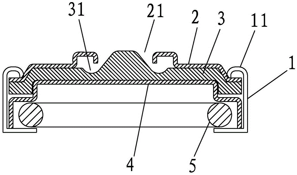
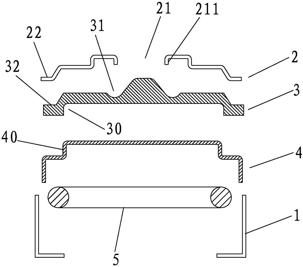
[0028] This case involves a new type of button, such as Figure 1-2 As shown, it mainly includes a buckle shell 1, a buckle cover 2, a buckle piece 3 and a buckle bottom 4. The buckle cover 2 , the buckle piece 3 and the buckle bottom 4 are closely stacked up and down sequentially, and the three are semi-enclosed and assembled by the buckle shell 1 . Copper ring 5 can be assembled in the button bottom 4 .

[0029] A convex step 40 is formed on the buckle bottom 4 , and the convex step 40 is preferably a circular convex column whose step surface is close to its own edge. The corresponding buckle 3 is formed with a concave step groove 30 for matching and embedding the convex step 40, and the buckle 3 is nested and matched with the concave step groove 30 by means of the convex step 40 to realize a tight and stable assembly with the buckle b...


PUM


Abstract

The invention discloses a novel button which comprises a button shell, a button bottom, a button piece and a button cover, wherein the button cover, the button piece and the button bottom are tightly overlapped in sequence from top to bottom and are encircled by the button shell in a semi-surrounding assembled manner; convex steps are formed in the button bottom; concave step grooves into which the convex steps can be embedded in a matched manner are formed in the corresponding button piece; clamping holes are formed in the button cover; a concave annular channel is formed in the side surface, facing the clamping holes, of the button piece. Due to the guidance function of the annular channel, and a button foot part is cracked and turned upwards, is embedded into the annular channel in a matched manner and is clamped by the clamping holes, so that a stable and solid buckling effect can be achieved. As the button cover, the button piece and the button bottom are tightly overlapped in sequence from top to bottom inside the button shell, the button bottom is embedded into the button piece in a matched manner through the convex steps and the concave step grooves, and the button piece is very solidly positioned between the button cover and the button bottom, the whole button is very compact in structural design and is good in adhesion to clothes when being assembled, and the outer surface of the button cover is relatively smooth and restraining.

Description

technical field [0001] The invention relates to the field of buttons, in particular to a novel button piece. Background technique [0002] The four-button button is a commonly used connecting tool for connecting two skirts together, and it mainly plays the role of fastening connection. Usually, the four-button button is divided into four buttons from top to bottom, the buckle surface, the buckle shell, the buckle bead, and the buckle foot. The buckle surface and the buckle shell are combined to form a female button assembly. There is a copper ring; the buckle and the buckle feet are combined to form a male buckle assembly, and a buckle protrudes from the middle of the male buckle, and the buckle is pressed into the buckle groove of the female buckle and then clamped by the copper ring to realize the connection. [0003] At present, in the structural design of the four-button button, the focus is only on the connection performance between the two sets of buttons (that is, be...

Claims


Application Information

Patent Timeline
Patent Type & Authority Applications(China)
IPC IPC(8): A44B17/00
CPCA44B17/0052
Inventor 吴朝旭孙德来庄君钰
Owner SHISHI LONGXIANG HARDWARE PLASTIC PROD CO LTD
Learn More