Power free lift type flood gate

A gate and electric technology, which is applied in the field of electric-free lift-up flood control gates, can solve the problems of complex overall mechanism and assembly, barriers to entry and exit of waterproof door panels, and inability to raise waterproof door panels.

Inactive Publication Date: 2016-06-15
曾立宇
View PDF7 Cites 3 Cited by
  • Summary
  • Abstract
  • Description
  • Claims
  • Application Information

AI Technical Summary

Problems solved by technology

[0007] In order to solve the problem that the existing electric-driven waterproof gate has complicated overall mechanism and assembly, and the waterproof door panel cannot be raised when the power is off. Raising the waterproof door panel first will cause access barriers when there is n

Method used


Image

  • Power free lift type flood gate
  • Power free lift type flood gate
  • Power free lift type flood gate

Examples


Embodiment Construction

[0036] In order to have a clearer understanding of the technical features, purposes and effects of the present invention, the specific implementation manners of the present invention will now be described with reference to the accompanying drawings.

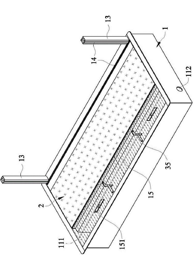
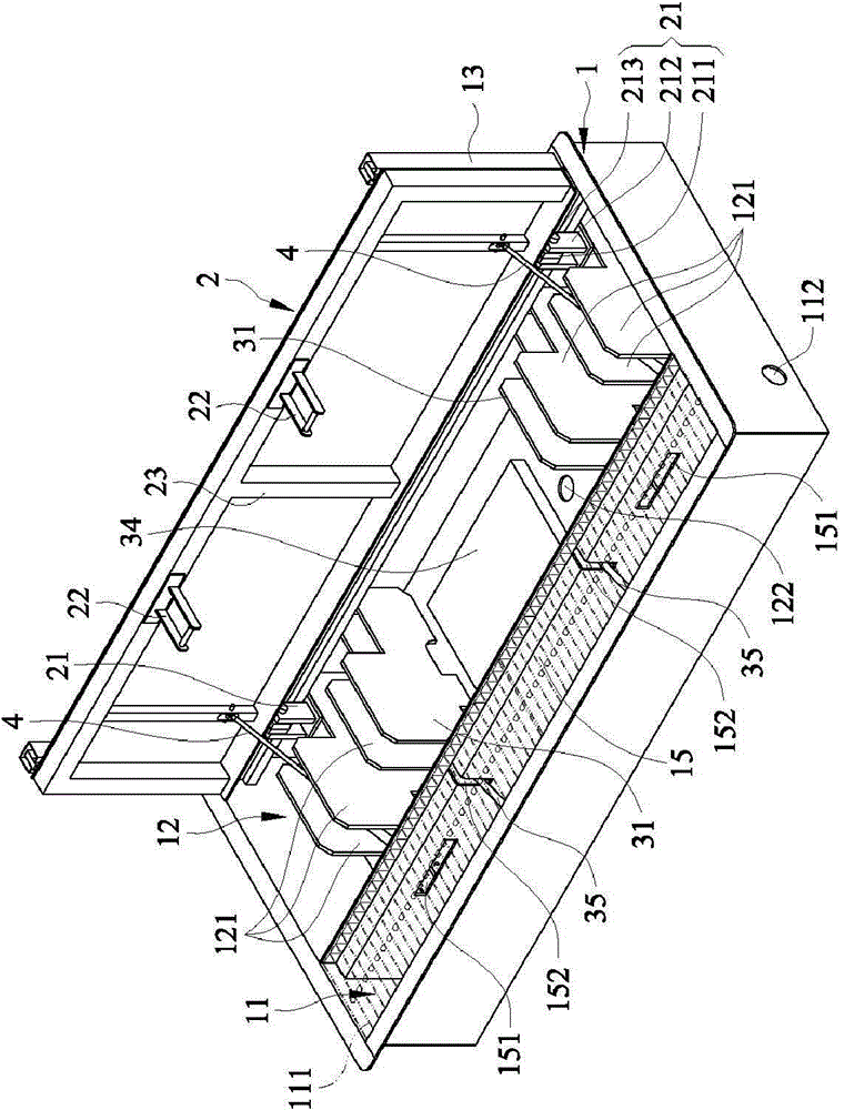
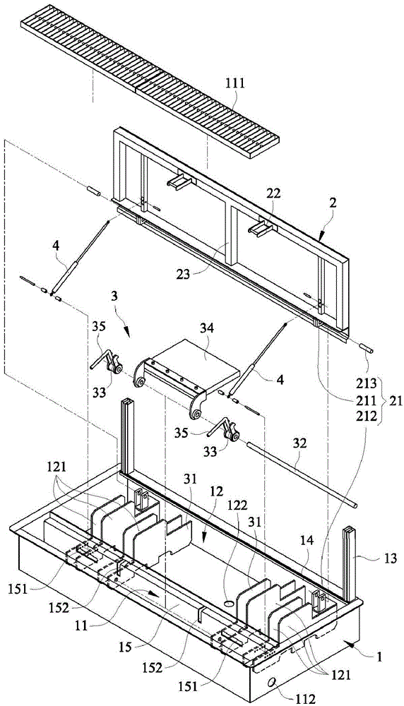
[0037] see Figure 1 to Figure 7 Shown are respectively the three-dimensional appearance schematic diagram of the closed state of the power-free lift-off flood control gate of the present invention, the three-dimensional appearance schematic diagram of the open state of the present invention, the three-dimensional exploded schematic diagram of the present invention, the top view state schematic diagram when the present invention is closed, and the closed state schematic diagram of the present invention. The schematic diagram of the sectional state when the present invention is opened, the schematic diagram of the top view state when the present invention is opened, and the schematic diagram of the cross-sectional state when the pr...


PUM


Abstract

The invention provides a power free lift type flood gate. The flood gate comprises a seat body comprising a first water collecting area and a second water collecting area; a waterproof gate, which is movably integrated on one side of the seat body and is used to open/close the second water collecting area; a float force interlink mechanism, which is arranged in the second water collecting area and is buckled to the waterproof gate; and at least two air pressure rods, which are arranged in the second water collecting area and connected to the waterproof gate. The flood gate can be arranged on the external side of inlet/outlet of a building. The waterproof gate and the ground of the inlet/outlet are in the same horizontal plane. When the water flowing from the first water collecting area to the second water collecting area reach a predetermined height, water is taken as the driving force to drive the float force interlink mechanism to release the waterproof gate so as to release the air pressure rods to lift the waterproof gate, the waterproof gate is lifted and is vertical to the ground, the waterproof gate baffles the water from entering the building, and thus the flood is prevented without any power operation.

Description

technical field [0001] The invention relates to an electric-free lift-off flood control gate, in particular to an electric-free lift-off flood control gate which can be used at the entrance and exit of a building to block water and prevent floods. Background technique [0002] Generally, in order to prevent flooding, waterproof gate equipment is usually installed at the entrance and exit of the building to prevent flooding from the gate and driveway, and the general waterproof gate equipment is usually composed of two sets corresponding to the entrance and exit The ㄈ-shaped guide rails on both sides, at least one waterproof door panel movably embedded in the ㄈ-shaped guide rail, and most of the knobs arranged on the ㄈ-shaped guide rail to lock the waterproof door panel; thus, the waterproof door panel can be used as a water-repellent use. [0003] However, because the waterproof door panel is used to block water, it is usually made of stronger metal material, so that the wa...

Claims


Application Information

Patent Timeline
IPC IPC(8): E02B7/26
Inventor 曾立宇
Owner 曾立宇
Why Eureka
Try Eureka