
Self-priming centrifugal pump

A self-priming centrifugal pump and centrifugal pump technology, applied in the field of water pumps, can solve the problems of difficult production and low operating efficiency

Inactive Publication Date: 2016-06-15
川源(中国)机械有限公司
View PDF5 Cites 2 Cited by
  • Summary
  • Abstract
  • Description
  • Claims
  • Application Information

AI Technical Summary

Problems solved by technology

Its disadvantage is that it is difficult to make and the operation efficiency is low.

Method used


Image

  • Self-priming centrifugal pump

Examples


Embodiment Construction

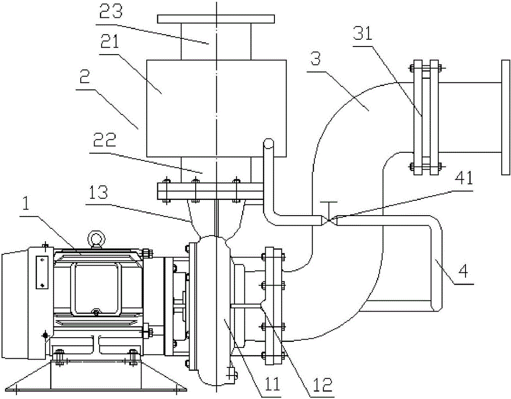
[0016] like figure 1 As shown, a self-priming centrifugal pump includes a centrifugal pump body 1, and the centrifugal pump body 1 is a common centrifugal pump structure, which is provided with an impeller chamber 11, and the impeller chamber 11 is provided with a water inlet 12. The water inlet 12 is connected and sealed with the water inlet pipe 3 and fixed by bolts, and a check valve 31 is installed on the water inlet pipe 3 .

[0017] In addition, the present invention adds an air-water separation barrel 2 on the basis of the ordinary centrifugal pump. The air-water separation barrel 2 is arranged above the pump body 1 of the centrifugal pump. The upper part of the impeller chamber 11 is provided with an upward protruding Interface 13, the upper interface 13 communicates with the impeller chamber 11, the bottom of the air-water separation barrel 2 is connected with the upper interface, the air-water separation barrel 2 is connected to a return water pipeline 4, and the ret...


PUM


Abstract

The invention discloses a self-priming centrifugal pump. The self-priming centrifugal pump comprises a centrifugal pump body, wherein the centrifugal pump body is provided with an impeller chamber which is provided with a water inlet, the water inlet is connected with a water inlet pipe, and a one-way valve is mounted on the water inlet pipe; the self-priming centrifugal pump is also provided with a gas-water separation bucket which is arranged above the centrifugal pump body; an upper interface which is upwards protruded is formed in the upper part of the impeller chamber, the upper interface communicates with the impeller chamber, and the bottom of the gas-water separation bucket communicates with the upper interface; the gas-water separation bucket is connected with a water return pipeline which communicates with the impeller chamber, and a self-operated regulating valve is arranged on the water return pipeline. According to the self-priming centrifugal pump disclosed by the invention, the gas-water separation bucket and the corresponding pipeline are additionally arranged based on a common centrifugal pump, so that the purpose that the common centrifugal pump has the self-priming function can be achieved, the application range of the common centrifugal pump is extended, the efficiency of the centrifugal pump is improved, and investment is reduced.

Description

technical field [0001] The present invention relates to water pumps. Background technique [0002] When the ordinary centrifugal pump works under negative pressure (with suction height), it needs to form a vacuum in the suction pipeline. The methods are as follows: [0003] 1. Install the bottom valve, fill the entire water inlet pipe with water, and empty the air in the water inlet pipe. Its disadvantage is that it is troublesome to operate, and the bottom valve provides water inlet resistance pump with low operating efficiency, and it is easy to block when it is used in sewage. [0004] 2. Install a vacuum pump and use the vacuum pump to empty the air in the water inlet pipeline. Its disadvantages are large investment, increased land occupation, and automatic control is not easy to realize. [0005] 3. Install the negative pressure vacuum water diversion tank, and use the volume of the vacuum water diversion tank to empty the air in the water inlet pipeline. Its disadv...

Claims


Application Information

Patent Timeline
Patent Type & Authority Applications(China)
IPC IPC(8): F04D9/02
CPCF04D9/02
Inventor 于金海
Owner 川源(中国)机械有限公司
Learn More