
Centrifugal pump with self-suction function and using method thereof

A technology for centrifugal pumps and functions, which is applied to components, pumps, and pump devices of elastic fluid pumping devices, and can solve the problems of inability to detect the temperature of centrifugal pump motors, inapplicability, and increased use costs.

Inactive Publication Date: 2021-05-11
阜阳鑫工机电设备有限公司
View PDF0 Cites 0 Cited by
  • Summary
  • Abstract
  • Description
  • Claims
  • Application Information

AI Technical Summary

Problems solved by technology

[0005] Aiming at the deficiencies of the prior art, the present invention provides a centrifugal pump with a self-priming function, which has the advantages of primary heat dissipation of the fan, advanced heat dissipation with the cooperation of water mist and the fan, and shock absorption of the centrifugal pump. When the temperature is high, the heat dissipation fan will also dissipate heat, wasting energy, and cannot perform secondary cooling and heat dissipation when the heat dissipation fan does not work, so that the service life of the centrifugal pump motor is reduced, and finally the temperature of the centrifugal pump motor cannot be detected. Prevent the internal rotor from being burned due to the high temperature of the centrifugal pump motor, damage the centrifugal pump motor, and increase the cost of use. In addition, the casing of the existing centrifugal pump impeller is generally fixed, and it cannot be applied to different installation environments.

Method used


Image

  • Centrifugal pump with self-suction function and using method thereof
  • Centrifugal pump with self-suction function and using method thereof
  • Centrifugal pump with self-suction function and using method thereof

Examples


Embodiment Construction

[0032] The following will clearly and completely describe the technical solutions in the embodiments of the present invention with reference to the accompanying drawings in the embodiments of the present invention. Obviously, the described embodiments are only some, not all, embodiments of the present invention. Based on the embodiments of the present invention, all other embodiments obtained by persons of ordinary skill in the art without making creative efforts belong to the protection scope of the present invention.

[0033] As introduced in the background technology, there are deficiencies in the prior art. In order to solve the above technical problems, the present application proposes a centrifugal pump with self-priming function.

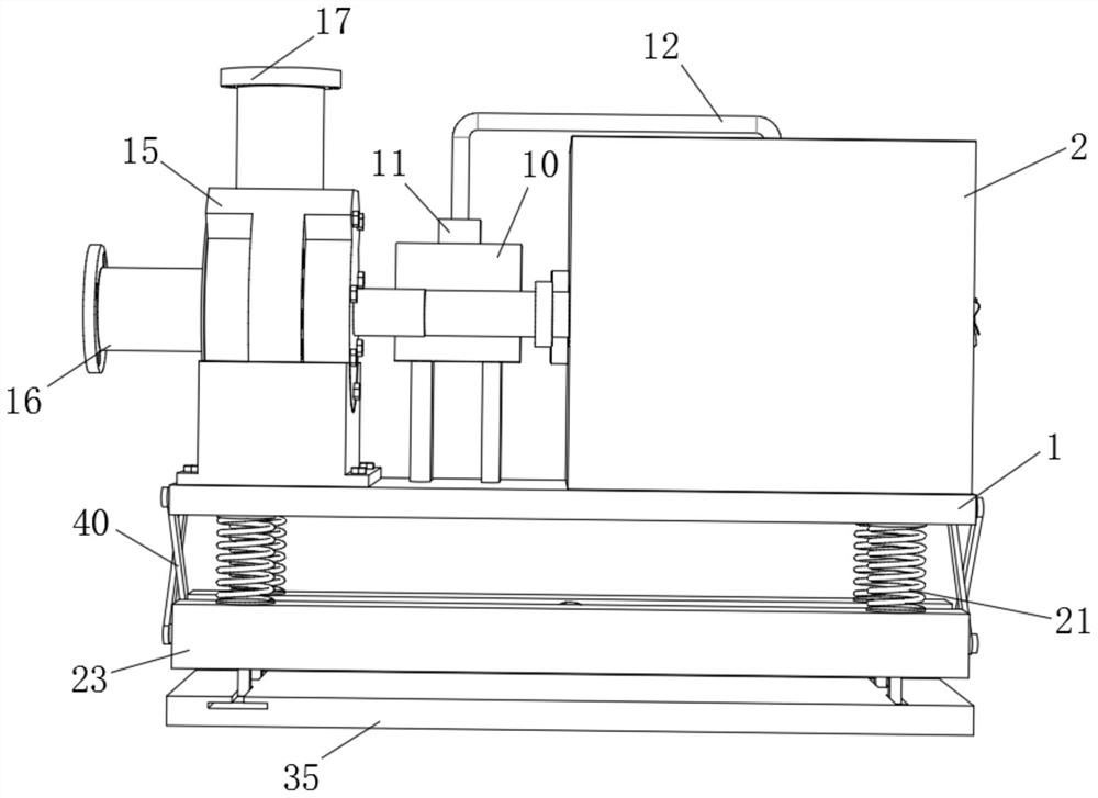
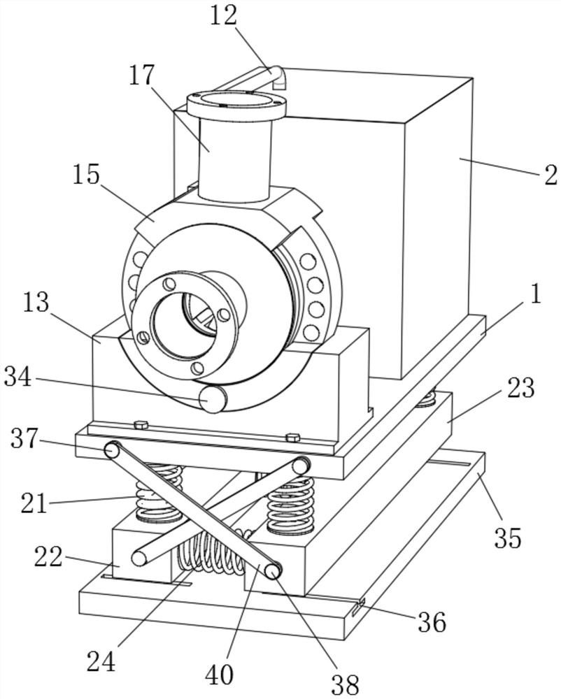
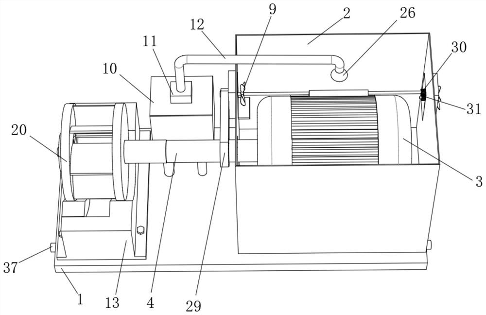
[0034] In a typical implementation of the present application, such as Figure 1-8As shown, a centrifugal pump with self-priming function includes a base 1 and a motor shield 2, the upper end of the base 1 is fixed with a motor 3 and a water ...


PUM


Abstract

The invention relates to the technical field of centrifugal pumps, and discloses a centrifugal pump with a self-suction function and a using method thereof.The centrifugal pump comprises a base and a motor protective cover, a motor is arranged in the motor protective cover, a primary fan heat dissipation and water mist spraying heat dissipation device is arranged in the motor protective cover, and a supporting frame is fixedly arranged on the side, opposite to the motor protective cover, of the upper end face of the base; and the top of the supporting frame is semicircular, a groove is formed in the middle of the top of the supporting frame, the top of the supporting frame is movably connected with an impeller shell, protrusions are arranged on the circumferential surface of the impeller shell, through holes are formed in the protrusions, damping springs are fixedly installed at the bottom of the base, and the damping springs and fixing strips are matched to form a multi-stage damping device. According to the centrifugal pump, fan heat dissipation and water spraying heat dissipation are installed in the motor protective cover, the combined use effect is better, in addition, the direction of the impeller shell can be adjusted at will, the centrifugal pump can be conveniently installed in different environments, and by means of the multi-stage damping device, it is prevented that when the centrifugal pump works, work is influenced by strong shaking.

Description

technical field [0001] The invention relates to the technical field of centrifugal pumps, in particular to a centrifugal pump with a self-priming function and a usage method thereof. Background technique [0002] When the centrifugal pump is working, the impeller is driven by the motor to rotate at a high speed, forcing the liquid between the blades to rotate at a constant angular velocity. Due to the centrifugal force, the liquid moves radially from the center of the impeller to the outer edge. Energy is obtained during the internal movement, and leaves the outer edge of the impeller at high speed and enters the volute pump casing. In the volute, due to the gradual expansion of the flow channel, it decelerates, and converts part of the kinetic energy into potential energy, and finally flows into the outlet pipe tangentially. . While the liquid is forced to be pushed from the center of the impeller to the outer edge, a low pressure is formed in the center of the impeller, s...

Claims


Application Information

Patent Timeline
IPC IPC(8): F04D13/06F04D29/58H02K9/00H02K9/06F04D29/62F04D29/42F04D29/66
CPCF04D13/06F04D29/426F04D29/5806F04D29/628F04D29/669H02K9/00H02K9/06
Inventor 郝俊飞郝良沛
Owner 阜阳鑫工机电设备有限公司
Learn More