
Shape measurement system and method of free-form surface optical element based on automatic tracking

An optical element and automatic tracking technology, which is applied in the field of measurement of aspheric surfaces and free surfaces, can solve problems such as surface damage and achieve the effect of compensating for damage

Active Publication Date: 2018-07-31
ZHEJIANG UNIV
View PDF8 Cites 0 Cited by
  • Summary
  • Abstract
  • Description
  • Claims
  • Application Information

AI Technical Summary

Problems solved by technology

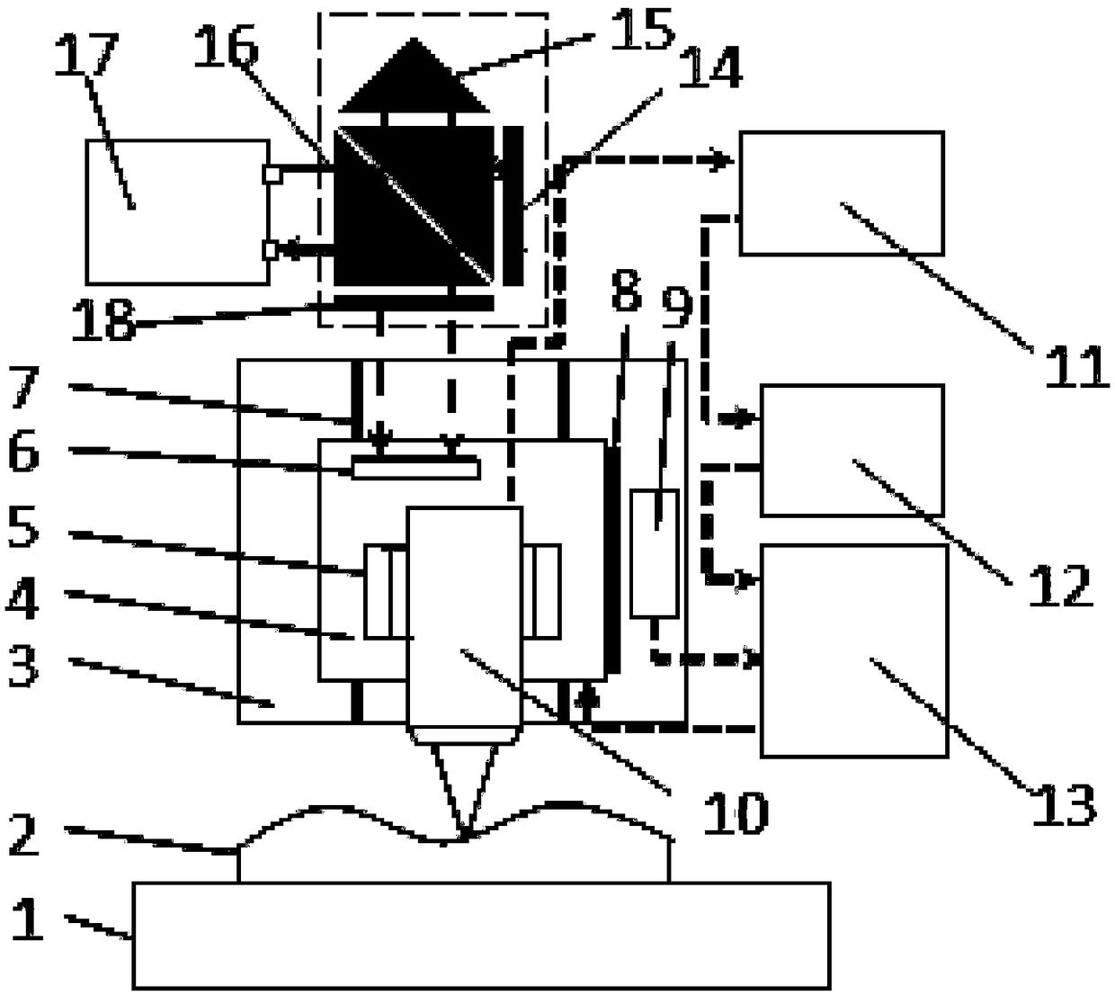
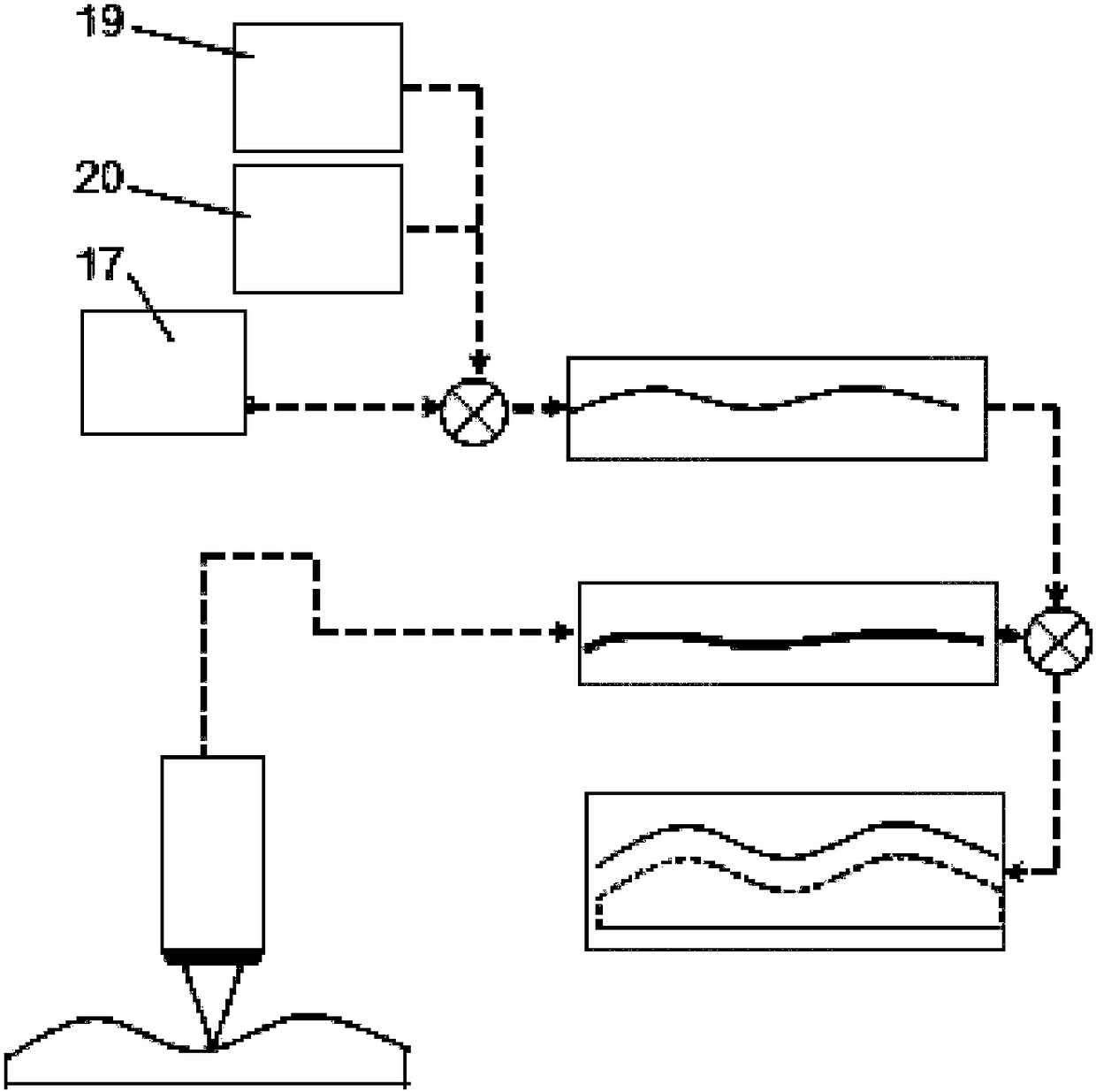
[0004] In order to solve the problem of damage to the surface that may be caused by contact measurement, and to improve the non-contact measurement accuracy, measurement range and scanning speed, the present invention proposes a free-form surface optical element shape measurement method based on the principle of automatic tracking

Method used


Image

  • Shape measurement system and method of free-form surface optical element based on automatic tracking
  • Shape measurement system and method of free-form surface optical element based on automatic tracking
  • Shape measurement system and method of free-form surface optical element based on automatic tracking

Examples


Embodiment

[0043] In the embodiment, a concave mirror with known design parameters is used to verify the accuracy of the measurement method. First place the concave mirror on the turntable, and then drive the turntable to move 18mm along the X-axis direction at a speed of 1mm / s through the pneumatic platform, then move 0.1mm along the Y-axis direction at a speed of 1mm / s, and then continue to move in the opposite direction along the X-axis Moving at the same speed, it moves back and forth in this way to realize S-shaped scanning, and the scanning range is 18mm*18mm. The result is as Figure 4 As shown, the difference between the measured parameters and the design parameters is about ±2um, which is within the tolerance range given by the concave mirror manufacturer.


PUM


Abstract

The invention discloses an automatic-tracking-based profile measurement system and method for a free-form-surface optical element. The system comprises a motion module, a position servo module and a dual-frequency laser interferometer. According to the invention, a profile of a measured optical element is obtained by fitting by using a measurement method of automatic probe tracking, so that a problem that the PV value can not be measured because the probe can not move according to the existing measurement method can be solved effectively. Meanwhile, with a color confocal measuring principle, the measurement precision and the resolution ratio can reach the nanometer scale and the measurement range can reach 10mm. Therefore, problems that the measured optical element may be damaged by the existing probe, the precision is low, and the range is limited in the prior art can be solved.

Description

technical field [0001] The invention relates to the field of non-contact optical three-dimensional shape measurement, in particular to the measurement of an aspheric surface and a free surface. Background technique [0002] Due to its advantages such as less distortion and lighter weight, free-form surface optical components have great market prospects and demands. At present, with the development of ultra-precision machining technology (including fast-tool servo, slow-tool servo and micro-milling, etc.), free-form surface processing has become possible, and the advanced manufacturing technology of free-form surfaces has created a premise for the application of free-form surfaces. Components are widely used in many fields, such as aerospace. Compared with the development of manufacturing and processing technology, the measurement method of free-form surface has not made great progress. The current measurement methods still mostly use contact measurement, such as Taylor Hob...

Claims


Application Information

Patent Timeline
Patent Type & Authority Patents(China)
IPC IPC(8): G01B11/24
CPCG01B11/24G01B11/2441
Inventor 居冰峰杜慧林曾培阳孙安玉孙泽青
Owner ZHEJIANG UNIV
Learn More