Outlet wire clamp device and permanent magnet motor with same

A wire clamp and motor body technology, applied in the field of permanent magnet motors, can solve the problems of reduced production efficiency, inconvenient production and use, and open welding of motor lead solder joints.

Inactive Publication Date: 2016-06-15
ZHUHAI GREE REFRIGERATION TECH CENT OF ENERGY SAVING & ENVIRONMENTAL PROTECTION
View PDF6 Cites 3 Cited by
  • Summary
  • Abstract
  • Description
  • Claims
  • Application Information

AI Technical Summary

Problems solved by technology

[0004] 1. The wire-passing groove of the wire clamp is a straight groove, and the lead wire cannot be clamped tightly, so that the lead wire is easily pulled, which may cause the internal solder jo

Method used


Image

  • Outlet wire clamp device and permanent magnet motor with same
  • Outlet wire clamp device and permanent magnet motor with same
  • Outlet wire clamp device and permanent magnet motor with same

Examples


Embodiment Construction

[0037] It should be noted that, in the case of no conflict, the embodiments in the present application and the features in the embodiments can be combined with each other. The present invention will be described in detail below with reference to the accompanying drawings and examples.

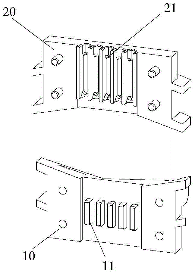
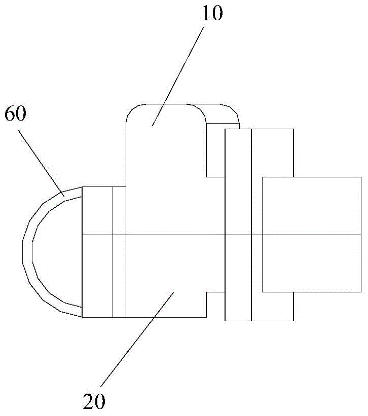
[0038] Such as figure 1 and figure 2 As shown, the present invention provides an outlet clamp device.

[0039] The outgoing wire clamp device of the present invention comprises a wire clamp upper piece 10 , a wire clamp lower piece 20 , a wire pressing protrusion 11 and a wire passing groove 21 .

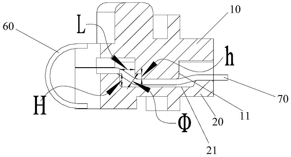
[0040] Specifically, such as Figure 1 to Figure 3 As shown, at least one thread-pressing protrusion 11 is provided on the inner surface of the upper piece 10 of the cable clamp, and the inner surface of the lower piece 20 of the cable clamp is provided with a thread-passing groove 21 matching the thread-pressing protrusion 11 . The wire-pressing protrusion 11 extends into the wire-passing groov...


PUM


Abstract

The invention provides an outgoing line clamp device and a permanent magnet motor with the same. The outlet wire clamp device includes: the upper piece of the wire clamp, the inner surface of which is provided with at least one pressing protrusion; the lower piece of the wire clamp, the inner surface of which is provided with a groove for passing through the line matching the pressing protrusion; Wherein, the wire-pressing protrusion cooperates with the wire-passing groove to form a wire-passing channel suitable for the lead wire and fix the lead wire. Since the wire-passing channel formed by the wire-pressing protrusion and the wire-passing groove is in the shape of a "bow" and is no longer a straight-line channel, the lead wire can be clamped, the lead wire is not easy to be pulled, and the solder joint inside the lead wire can be avoided. The outgoing line clip device of the present invention is simple in structure, safe and reliable.

Description

technical field [0001] The invention relates to the field of electrical appliances, in particular to an outgoing wire clamp device and a permanent magnet motor with the same. Background technique [0002] Existing motors generally mainly include a stator assembly, a rotor assembly, an end cover, a power board, and outlet clamps. The wires are led out of the motor through the wire slot through the outlet wire clamp, and the wire clamp is placed in the fixed position of the stator assembly, and fixed and pressed with the end cover. [0003] At present, the existing wire clamps generally have the following problems: [0004] 1. The wire-passing groove of the wire clamp is a straight groove, and the lead wire cannot be clamped tightly, so that the lead wire is easily pulled, which may cause the internal solder joints of the motor lead wire to open welding; [0005] 2. The upper piece and the lower piece of the wire clamp are separated, which is inconvenient to produce and use,...

Claims


Application Information

Patent Timeline
IPC IPC(8): H02K5/22H02K3/50
Inventor 许金鑫李庆邱东霖王庆凯张之元王周叶张小波
Owner ZHUHAI GREE REFRIGERATION TECH CENT OF ENERGY SAVING & ENVIRONMENTAL PROTECTION
Why Eureka
Try Eureka