
Operation method of bean grinding coffee machine for rotationally brewing

一种工作方法、旋转冲泡的技术,应用在饮料制备装置、家里用具、应用等方向,能够解决不能实现一次加水多次使用、性能不可靠、使用寿命短等问题,达到结构简单合理、性能可靠、降低操作难度的效果

Inactive Publication Date: 2016-06-22
周林斌
View PDF7 Cites 2 Cited by
  • Summary
  • Abstract
  • Description
  • Claims
  • Application Information

AI Technical Summary

Problems solved by technology

This structure uses electronic components to convert the liquid channel, which is prone to failure or requires program control, resulting in unreliable performance and short service life. Therefore, further improvement is necessary
[0003] Ordinary bean grinding coffee pots must be cleaned once when used, adding water and adding beans each time, the frequency is high and the operation is cumbersome, and it is impossible to add water once or add beans once and use it multiple times. Therefore, it is necessary to make further improvements

Method used


Image

  • Operation method of bean grinding coffee machine for rotationally brewing
  • Operation method of bean grinding coffee machine for rotationally brewing
  • Operation method of bean grinding coffee machine for rotationally brewing

Examples


no. 1 example

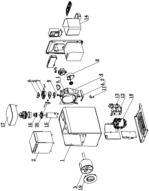
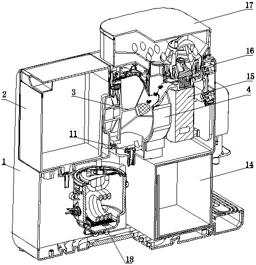
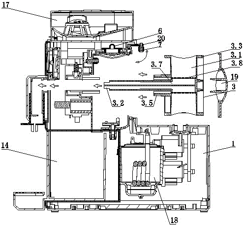
[0060] First embodiment (see Figure 1-Figure 15 , Figure 18 )

[0061] The working method of a coffee grinder with rotary brewing includes a body 1, a water tank 2, a water supply assembly, a grinding assembly and a brewing assembly; the body 1 is provided with a brewing chamber and a grinding chamber, and the brewing assembly and The grinding assembly is respectively placed in the brewing chamber and the grinding chamber; the brewing assembly includes a rotatable rotating part 3, and two brewing chambers 3.1 are symmetrically arranged in the rotating part 3, and the opening of the brewing chamber 3.1 rotates in a circular track The brewing component is provided with a brewing head opening 4.2 and a material outlet 4.1, the water outlet of the water supply component and the powder outlet of the grinding component respectively pass through the brewing head opening 4.2, the material outlet 4.1 and the opening of the barrel brewing chamber 3.1; The opening of the brewing cham...

no. 3 example

[0080] Third embodiment (see Figure 17 )

[0081] The working method of this rotary brewing bean grinder coffee machine is different from the first embodiment in that the grinding cutter 16 adopts a blade.

[0082] Other parts not described are the same as those of the first embodiment, and will not be analyzed and described here.

[0083] Fourth embodiment (see Figure 19 )

[0084] The working method of the rotary brewing bean grinder coffee machine is different from the first embodiment in that: one brewing chamber 3.1 is provided in the rotating member 3 and placed on one side of the axis.

[0085] Other parts not described are the same as those of the first embodiment, and will not be analyzed and described here.

[0086] Fifth embodiment (see Figure 20 )

[0087] The working method of the rotary brewing coffee grinder differs from the first embodiment in that: the rotating member 3 is fan-shaped, and a brewing chamber 3.1 is provided, and the brewing chamber 3.1 ...


PUM


Abstract

The invention discloses an operation method of a bean grinding coffee machine for rotationally brewing. The method comprises the following steps: inserting or putting a liquid discharge hole in a rotating piece, a coffer outlet or an opening of a brewing cavity which points the outer part into a body, to form transmission connection with a rotating bracket, and hanging the rotating piece through a hook to form rotation connection, or rotating the hook to be turned to the inner side or the bottom of the rotating piece to hang the rotating piece to form rotation connection, and closing a cover or a limiting piece; ensuring that the opening of the brewing cavity on the rotating piece rotates in a circular or fan-shaped track to be communicated with a material outlet after power is on, and then performing closing down; ensuring that a grinding chamber passes through a grinding motor, a grinding tool and a bean cavity, the grinding motor is axially connected with the grinding tool to grind coffee beans, and ground coffee enters the brewing cavity through the material outlet, so as to fill the brewing cavity. The method ensures that the coffee feeding, brewing and discharging procedures can be automatically, continuously and circularly performed by rotationally arranging the rotating piece, and realizes the requirement of full automation.

Description

technical field [0001] The invention relates to a coffee machine, in particular to a working method of a rotary brewing coffee grinder. Background technique [0002] Chinese Patent Document No. CN203828724U disclosed a fully automatic liquid passage conversion device on September 17, 2014, which specifically disclosed that it includes: at least two liquid passages and conversion shafts for switching the conduction or closure of the above passages The motor is used to drive the conversion shaft, and the liquid path conversion signal circuit is connected to the conversion shaft to generate an electrical signal for the position of the conversion shaft; the controller is used to receive the electrical signal sent by the circuit and instruct The motor selectively rotates or stops rotating to realize the conduction or closure of the above passage; the liquid passage conversion signal circuit includes a rotating plate, which is connected with the conversion shaft in a manner that c...

Claims


Application Information

Patent Timeline
Patent Type & Authority Applications(China)
IPC IPC(8): A47J31/42A47J31/44
CPCA47J31/00A47J31/06A47J31/106A47J31/18A47J31/24A47J31/40A47J31/402A47J31/404A47J31/405A47J31/408A47J31/42A47J31/44A47J31/4403A47J31/4407A47J31/46A47J31/467A47J31/54A47J31/60
Inventor 周林斌
Owner 周林斌
Learn More