Self-dust-collecting dust collector

A vacuum cleaner and dust collection technology, which is applied in the direction of vacuum cleaners, suction nozzles, cleaning equipment, etc., can solve problems such as deficiencies, and achieve the effect of reasonable structure, low noise, and clean discharge

Active Publication Date: 2016-06-22
NINGBO HAIJI ELECTRIC APPLIANCE
View PDF6 Cites 2 Cited by
  • Summary
  • Abstract
  • Description
  • Claims
  • Application Information

AI Technical Summary

Problems solved by technology

However, the current vacuum cleaners are still lacking in the rationality of the internal air duct setting, the separation ability of dust and air, and the separation effect.

Method used


Image

  • Self-dust-collecting dust collector
  • Self-dust-collecting dust collector
  • Self-dust-collecting dust collector

Examples


Embodiment 1

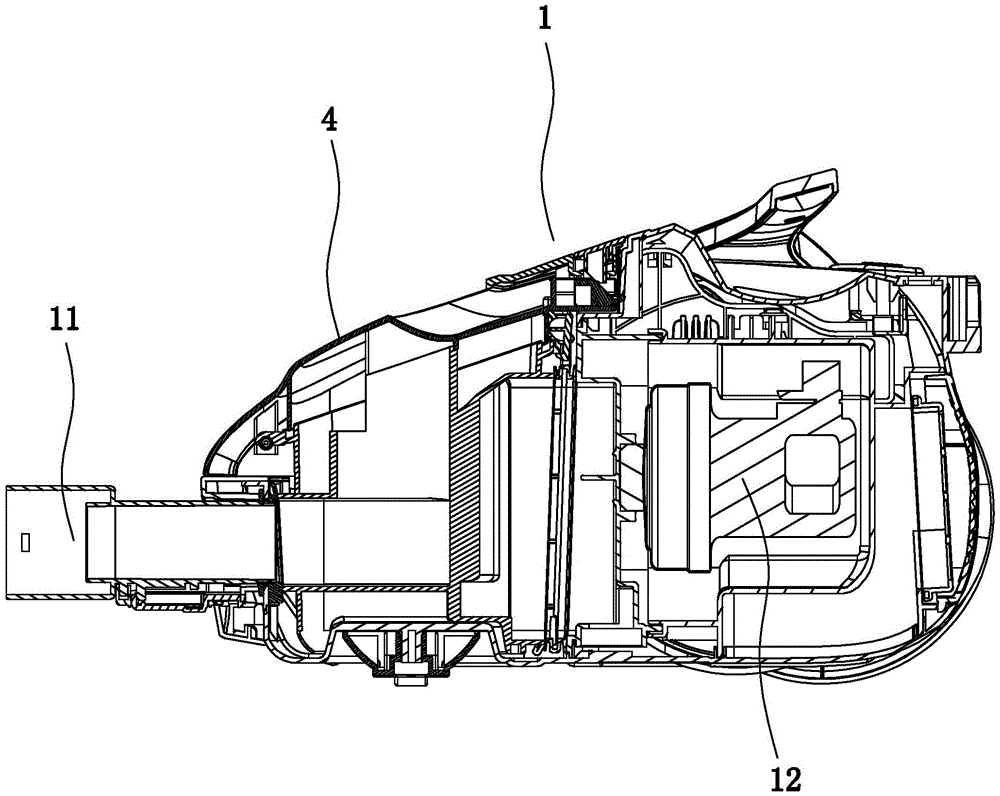
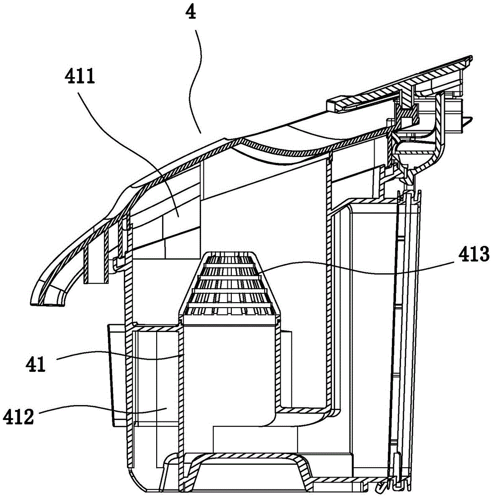
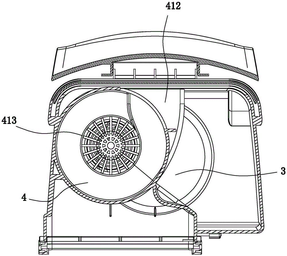
[0022] Embodiment 1: as Figure 1 to Figure 3 In the shown embodiment, a self-dust collecting vacuum cleaner includes a main body 1 and a dust mop 2. The main body is provided with a side dust cup 3, a cyclone separation cylinder 4, and a body air inlet pipe 11. A motor cavity is provided, and a suction motor 12 is arranged in the motor cavity. A vertical spin-assist inner cylinder 41 is arranged in the cyclone separation cylinder. To the air inlet, side dust outlet 411, the side dust outlet is connected to the side dust cup, the side dust outlet is higher than the transverse air inlet, the upper end of the spin-assist inner cylinder is higher than the transverse air inlet, and the upper end of the spin-assist inner cylinder The opening communicates with the inside of the cyclone separation cylinder, the opening at the lower end of the spin-assisted inner cylinder communicates with the air inlet end of the suction motor, the transverse air inlet communicates with the air inlet...

Embodiment 2

[0027] Embodiment 2: the basic structure and implementation mode of this embodiment are the same as embodiment 1, and its difference is, as Figure 4 to Figure 7 As shown in , the dust-absorbing mop is provided with several rear ground wheels 23 and at least one front ground wheel 24, and the bottom of the dust-absorbing mop is provided with a direct suction port 25, and the air intake direction of the direct suction port is upward, and the inside of the mop is The air duct is communicated with the direct suction inlet, and the dust-absorbing mop is provided with a brush bar 261 for brushing the ground, and the brush bar is in front of the direct suction inlet. The air duct inside the floor mop is connected to the air inlet pipe of the fuselage through a vacuum hose (it can also be connected through other structures, as long as the air sucked into the air duct inside the mop can enter the air inlet pipe of the fuselage). The rear ground wheel and the front ground wheel are con...


PUM


Abstract

The invention discloses a self-dust-collecting dust collector which comprises a main machine body and a dust collection mop. A side dust cup, a cyclone separation cylinder and a machine body air inlet pipe are installed on the main machine body. A motor cavity is formed in the main machine body, an air suction motor is arranged in the motor cavity, a vertical rotation-assisting inner cylinder is arranged in the cyclone separation cylinder, the upper end and the lower end of the rotation-assisting inner cylinder are provided with openings, the side wall of the cyclone separation cylinder is provided with a transversely cut air inlet and a side dust discharge opening, the side dust discharge opening is communicated with the side dust cup, the side dust discharge opening is higher than the transversely cut air inlet, the upper end of the rotation-assisting inner cylinder is higher than the transversely cut air inlet, the opening in the upper end of the rotation-assisting inner cylinder is communicated with the cyclone separation cylinder, the opening of the lower end of the rotation-assisting inner cylinder is communicated with the air inlet end of the air suction motor, the transversely cut air inlet is communicated with the machine body air inlet pipe, and the air outlet end of the air suction motor is communicated with an external exhaust port in the main machine body. The dust collector has the advantages that the functions of dust collection, separation and air exhaust can be effectively completed, the dust collection capacity is high, dust can be automatically isolated and compressed, and discharge cleanliness is guaranteed.

Description

technical field [0001] The invention belongs to the technical field of vacuum cleaners, in particular to a self-dust collecting vacuum cleaner. Background technique [0002] With the development of the times and the improvement of living standards, vacuum cleaners, especially household vacuum cleaners, have been widely used. A vacuum cleaner is an electrical appliance that uses a motor (suction motor) to generate negative air pressure in a sealed housing to suck in dust or garbage. The main function of the current vacuum cleaner is to recycle and clean up the dust and garbage on the floor, carpet, etc. in the home. However, the current vacuum cleaners are still lacking in the rationality of the internal air duct setting, the separation ability and separation effect of dust and air. Contents of the invention [0003] In order to overcome the deficiencies in the prior art, the present invention provides a reasonable structure, which can effectively complete the functions o...

Claims


Application Information

Patent Timeline
Patent Type & Authority Applications(China)
IPC IPC(8): A47L5/22A47L9/06
CPCA47L5/22A47L9/06
Inventor 周荣郑良宝
Owner NINGBO HAIJI ELECTRIC APPLIANCE
Why Eureka
Try Eureka