Layered dairy cow feeding system and feeding method

A layered, dairy technology, applied in animal feeding devices, animal houses, other equipment, etc., can solve problems such as affecting the health of the herd, consuming manpower and material resources, and increasing the probability of bringing in germs.

Active Publication Date: 2020-10-20
SOUTH CHINA UNIV OF TECH
View PDF26 Cites 0 Cited by
  • Summary
  • Abstract
  • Description
  • Claims
  • Application Information

AI Technical Summary

Problems solved by technology

[0006] In addition to the above disadvantages, the existing feeding methods also have the following disadvantages: ① On the one hand, the feeding area and the living area of ​​the cattle are mixed together, which may easily cause feed pollution and affect the health of the cattle
②On the other hand, the existing feeding methods require staff to frequently enter the cowshed for feeding operations, which increases the probability of bringing in germs, or causes cross-infection between humans and cows
③Residual feed cleaning problem
Because dairy cows do not eat old and dry feed, the remaining feed after the cows eat needs to be cleaned up manually or by machines, which is inefficient; and the trough needs to be cleaned regularly to prevent the feed from mildew and bacteria, and keep the barn clean
These will increase the cost of breeding and consume a lot of manpower and material resources
Moreover, most of the existing dairy farms need to configure an additional cow manure treatment system, which is costly

Method used


Image

  • Layered dairy cow feeding system and feeding method
  • Layered dairy cow feeding system and feeding method
  • Layered dairy cow feeding system and feeding method

Examples


Embodiment Construction

[0043] The purpose of the invention of the present invention will be described in further detail below in conjunction with the accompanying drawings and specific embodiments, and the embodiments cannot be repeated here one by one, but the implementation of the present invention is not therefore limited to the following embodiments.

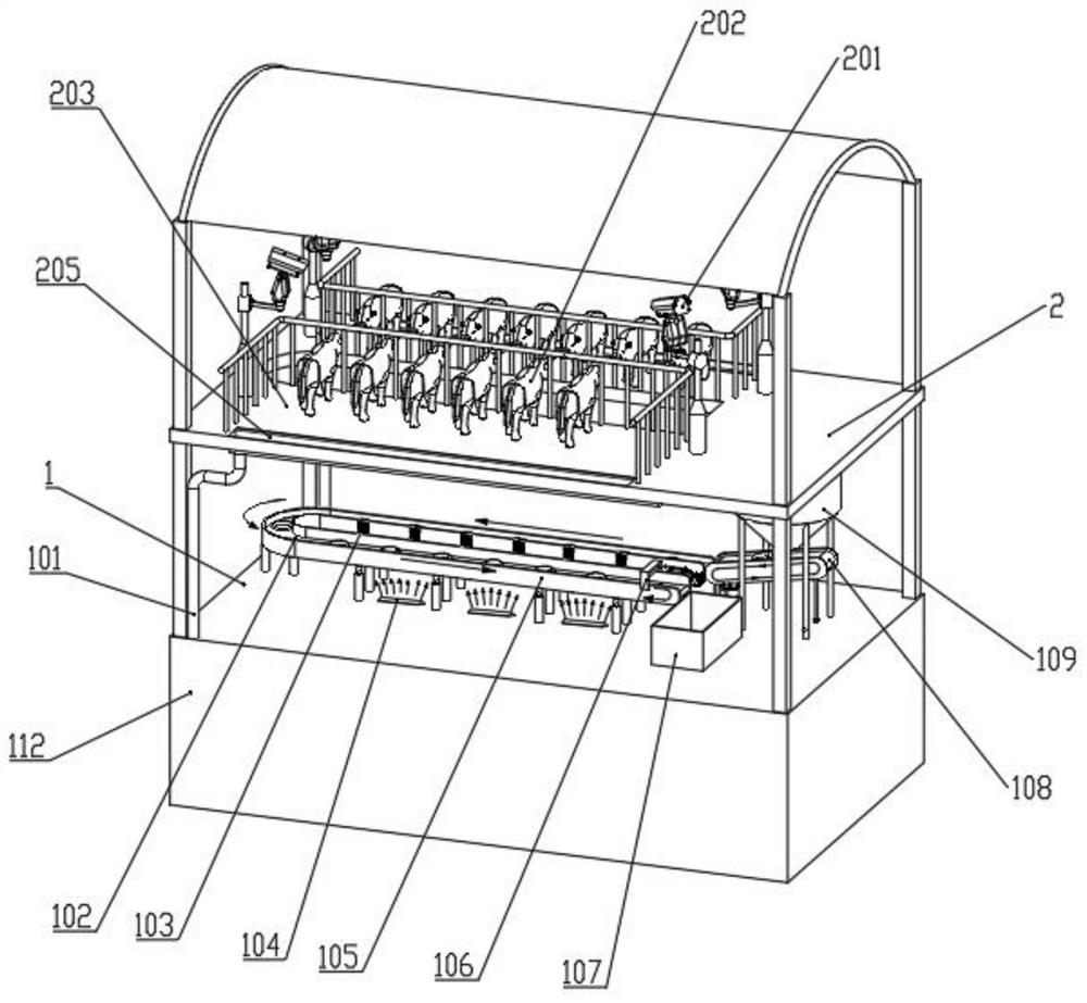
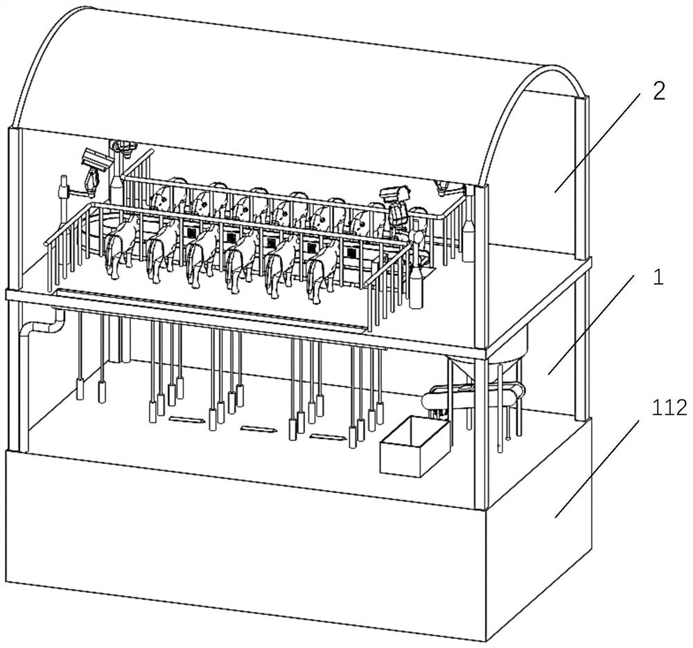
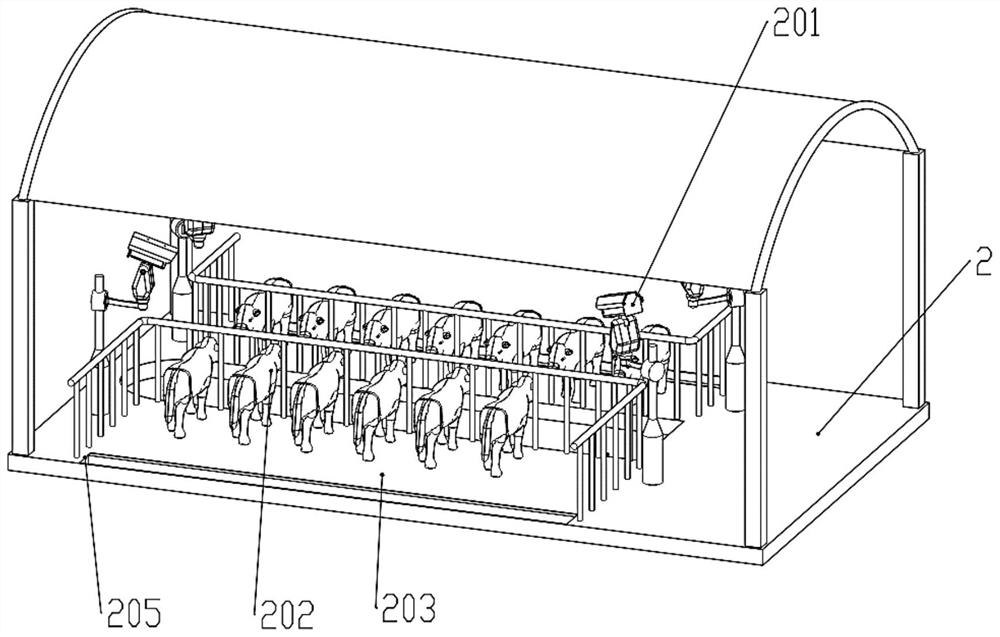
[0044] like figure 1 and figure 2 A layered cow feeding system shown includes a feeding layer 2 and a feed supply layer 1; the feeding layer 2 and the feed supply layer 1 are separated by a partition layer to form an upper and lower independent space layer; An opening is provided in the middle of the partition layer, and a partition 204 is provided at the opening. The partition 204 moves laterally under the push of the driving motor 206 . After the partition 204 moves to one side, the feeding layer 2 communicates with the feed supply layer 1 .

[0045] like Figure 4 and Figure 5 As shown, the feed supply layer 1 includes a batching machine 1...


PUM


Abstract

The invention provides a layered dairy cow feeding system and a feeding method. The system comprises a feeding layer and a feed supply layer, the feeding layer and the feed supply layer are separatedby a separation layer to form an upper space layer and a lower space layer which are independent; an opening is formed in the middle of the partition layer, and a partition plate is arranged at the opening and connected with a driving motor; the feed supply layer comprises a dosing machine, a trough, a feed recovery box and a trough conveyor belt cleaning device; the trough is located below the partition plate. The dosing machine conveys feed to the trough through the inclined conveying belt; and the feeding layer comprises a plurality of groups of cameras and cowsheds. The method comprises the following steps: 1, determining a feed formula by a dosing machine; 2, a trough conveying belt and an inclined conveying belt starting to operate; 3, after the trough is lifted to the feeding layer,the dairy cow starting to eat; according to the method, feed mixing, catering, conveying, recycling, trough cleaning and disinfection operations are completed on a feed supply layer, and dairy cow feeding, feeding monitoring and feedback operations are completed on a feeding layer.

Description

technical field [0001] The invention relates to the field of cow feeding, in particular to a layered cow feeding system and a feeding method. Background technique [0002] Dairy cow feeding is an important link in the dairy farming industry. At present, there are three feeding methods for dairy cows in my country, traditional artificial feeding, TMR feeding and robot feeding. [0003] Traditional artificial feeding refers to the separate feeding of coarse and concentrated feeds. Feeding personnel feed alfalfa, silage, roots, dregs and concentrated feeds to cows separately, relying on human labor to put feed. Since dairy cows need to be fed 3 to 4 times a day, artificial feeding requires a lot of labor input, high labor costs, and low feeding efficiency. And it is also necessary to manually clean up the remaining feed after the cows eat to prevent mildew, which greatly increases the workload of the breeder. At present, most of the small and medium-sized dairy farms in my co...

Claims


Application Information

Patent Timeline
IPC IPC(8): A01K5/02A01K1/00A01K1/01A01K67/02A01K29/00
CPCA01K5/0208A01K1/00A01K1/01A01K1/0132A01K67/02A01K29/005
Inventor 任海林张勤马赐文
Owner SOUTH CHINA UNIV OF TECH
Why Eureka
Try Eureka