
Filter Element That Has Plenum Containing Bonded Continuous Filaments

a filter element and continuous filament technology, applied in the direction of filtration separation, separation process, breathing protection, etc., can solve the problems of shortening the service life of filters early, and achieve the effect of reducing energy requirements, reducing pressure drop, and rapid fluid flow

Active Publication Date: 2007-06-28
3M INNOVATIVE PROPERTIES CO
View PDF53 Cites 37 Cited by
  • Summary
  • Abstract
  • Description
  • Claims
  • Application Information

AI Technical Summary

Benefits of technology

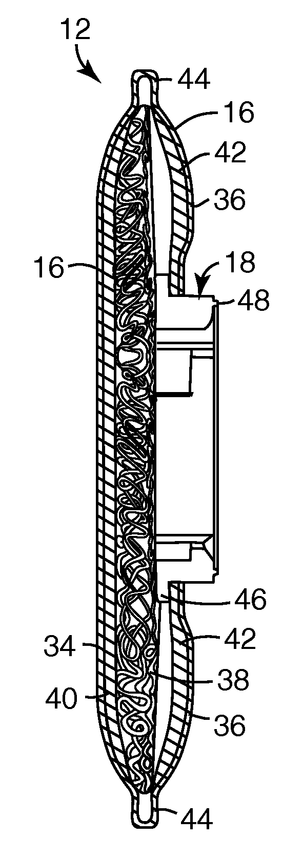
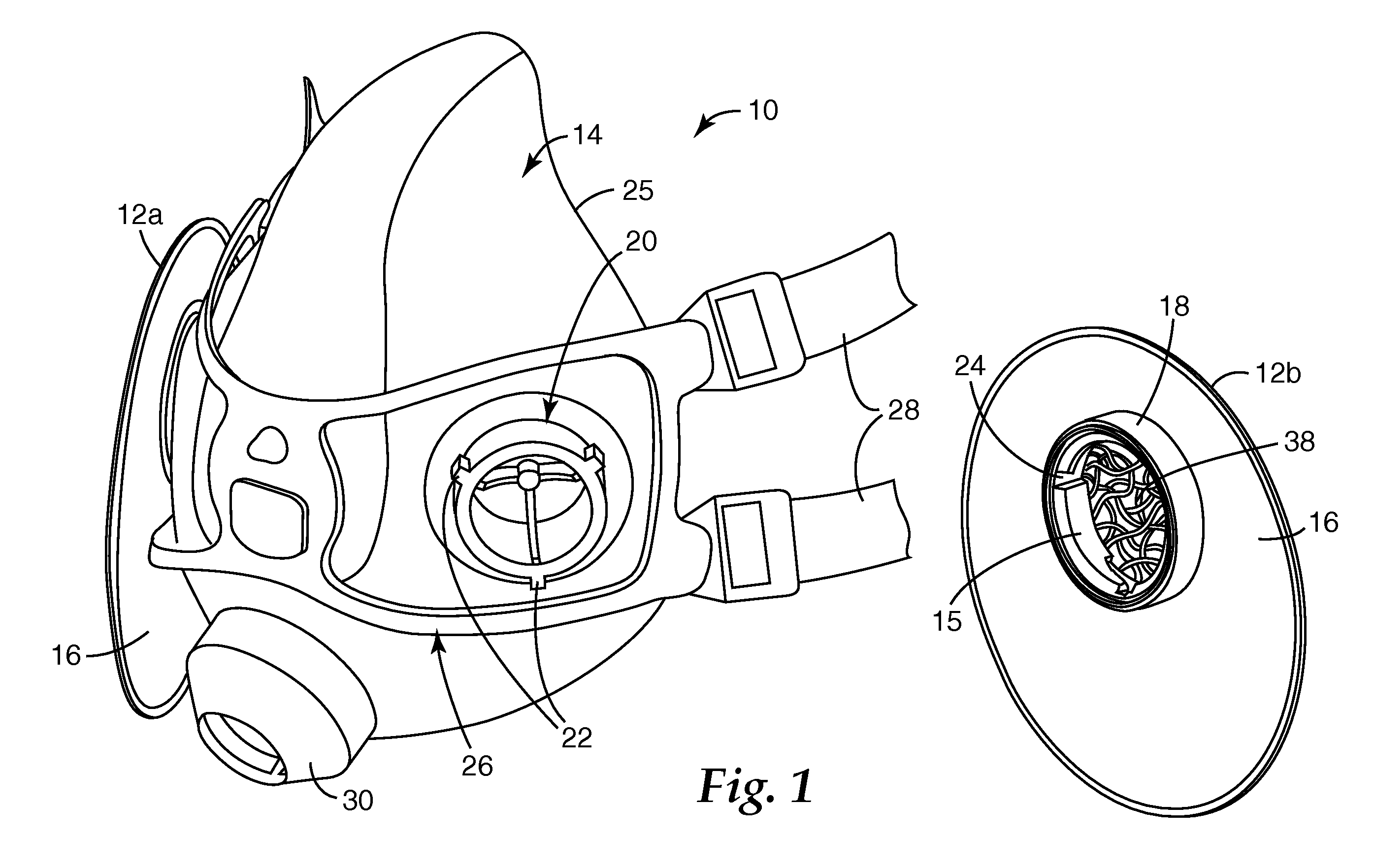
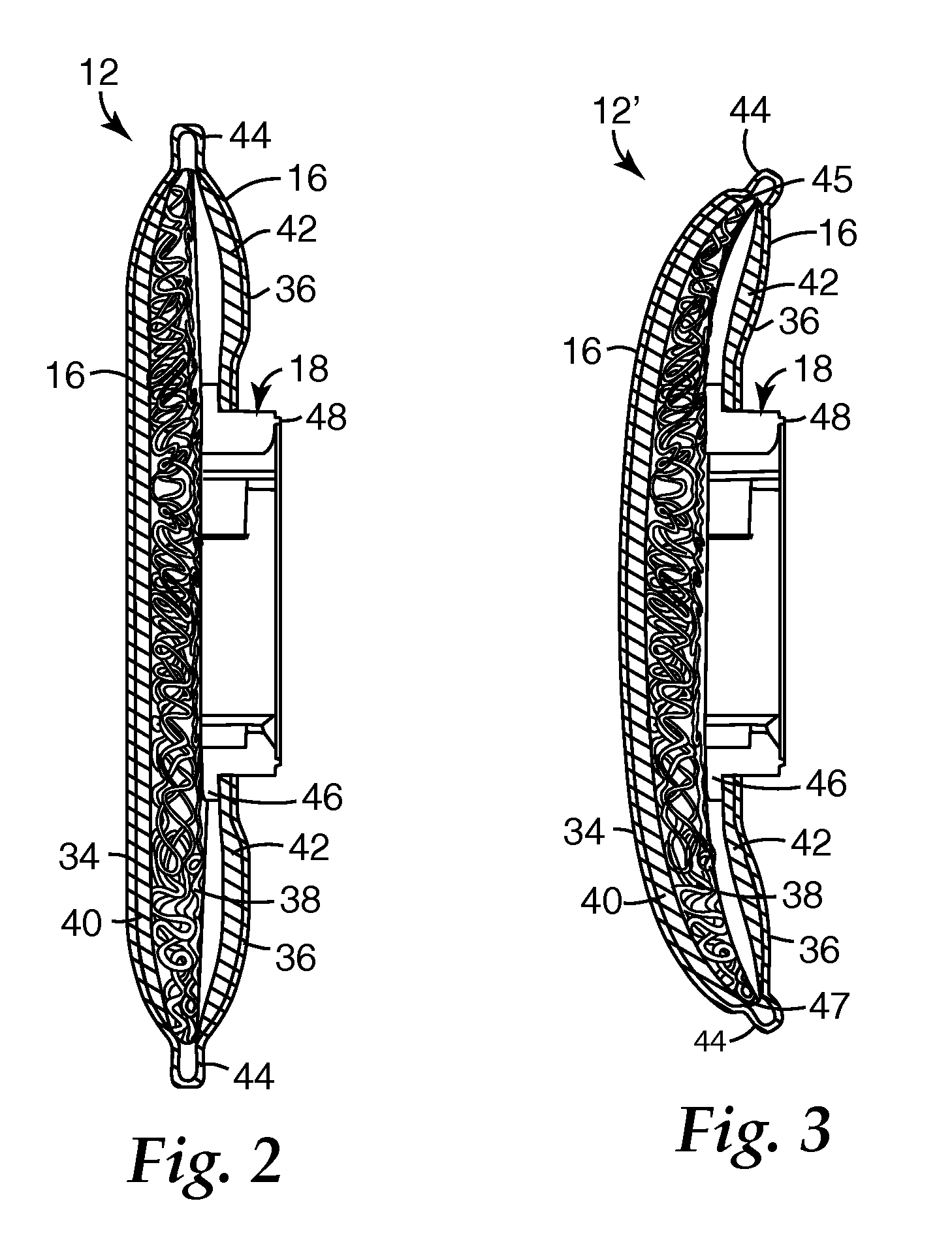
[0007] The present invention differs from known filter elements in that the invention includes a plenum that has continuous filaments that are bonded to each other at points of filament intersection. The inventors discovered that the use of such a plenum provides a variety of benefits to the filter element. The plenum enables the filter element to achieve a rapid distribution of fluid flow across the filter media without causing a substantial pressure drop increase. Because continuous filaments are used, which filaments are bonded to each other at points of fiber intersection, less filaments may be used volumetric-wise in the construction of the plenum. The use of fewer filaments provides less restriction to fluid flow. And when a fluid moves more freely through the plenum, there is less pressure drop across this portion of the filter element. As indicated above, lower pressure drops are beneficial in that they reduce the energy requirements needed to draw a fluid through the filter element. The need for less energy is particularly advantageous in “negative pressure respirators”, which, by definition, use a wearer's lungs as the power source that causes fluid flow through the filter element. Additionally, the inventive plenum is beneficial in that it can be contorted into a variety of configurations without being compressed. Resistance to compression is important for filtration operations because it preserves lateral fluid flow through the plenum and thereby prevents non-uniform fluid distribution patterns and pressure drop increases. Because of its ability to be contorted without substantial compression, the inventive plenum can be intentionally fashioned into a curved configuration that can enable the filter element to, for example, be attached more closely to the respiratory mask to not cause a large downward moment from gravitational force when worn and to remain out of a respirator wearer's field of vision.

Problems solved by technology

If the air-to-be-filtered is not uniformly distributed over the filter media during the filtering operation, the filtered particles may become unevenly collected by the filter, resulting in an early shortening of filter service life.

Method used


Image

  • Filter Element That Has Plenum Containing Bonded Continuous Filaments
  • Filter Element That Has Plenum Containing Bonded Continuous Filaments
  • Filter Element That Has Plenum Containing Bonded Continuous Filaments

Examples


example 1

[0066] A plenum web of the invention was produced by the method generally described in U.S. Pat. No. 5,733,825. The plenum web was polyester, 3M type 4430-6x20, Spacer Web available from 3M Company, St. Paul, Minn. The plenum web was configured with filter media and formed into a filter as described in the General Filter Element Making Procedure above. The front and rear faces of the filter element were filter media manufactured by Hollingsworth & Vose Co., Walpole, Mass. Grade TR0612J2. This material had a cover web which was oriented to the outside of the filter element. Filter elements constructed as described were evaluated for lateral air flow properties while under compressive loading as prescribe in the Compression Flow Bench Test procedure. Results are given in Table 1.


PUM

PropertyMeasurementUnit
Fractionaaaaaaaaaa
Fractionaaaaaaaaaa
Fractionaaaaaaaaaa

Abstract

A filter element 12 that includes a fluid inlet 16, a fluid outlet 17 that is in fluid communication with the inlet 16, a filter media 40, 42 through which the fluid passes when moving from the inlet 16 to the outlet 17, and a plenum 38 that comprises continuous filaments 66 that are bonded to each other at points of filament intersection 68. The plenum is easy to manufacture, is resistant to compaction when contorted, and exhibits a low pressure drop as air is distributed across the filter media.

Description

[0001] The present invention pertains to a filter element that uses a new plenum for managing fluid flow across a filter media. The plenum comprises continuous filaments that are bonded to each other at points of filament intersection. The filter element may, for example, take the form of a filter cartridge that is attached to a respirator. BACKGROUND [0002] Persons who work in contaminated environments commonly wear respirators to protect themselves from inhaling contaminants that are suspended in the surrounding air. The respirators—also referred to as “filtering face masks”—may have a filter element integral to the mask body (see, for example, U.S. Pat. No. 5,307,796 to Kronzer et al.) or separately attachable (see, for example, U.S. Pat. No. 5,579,761 to Yuschak et al.). In either instance, the respirator must comfortably provide the wearer with protection from airborne particles or unpleasant or noxious gases over the useful service life of the filter element. To achieve this g...

Claims


Application Information

Patent Timeline
IPC IPC(8): B01D50/00
CPCA62B23/02A62B23/00B01D46/10B01D2275/10B01D39/1623
Inventor ANGADJIVAND, SEYED A.MARTIN, PHILIP G.RUNNING, DAVID B.
Owner 3M INNOVATIVE PROPERTIES CO
Learn More