
Auxiliary equipment for display substrate testing and display substrate testing method

A technology for display substrates and auxiliary equipment, which is applied in printed circuit testing, electronic circuit testing, etc., and can solve the problems of low design utilization rate, low efficiency, and increased manufacturing cost of display substrates.

Active Publication Date: 2018-05-18
BOE TECH GRP CO LTD
View PDF5 Cites 0 Cited by
  • Summary
  • Abstract
  • Description
  • Claims
  • Application Information

AI Technical Summary

Problems solved by technology

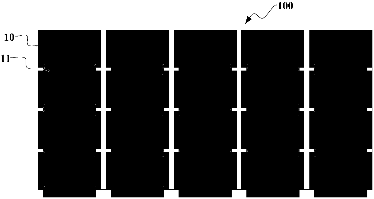
[0003] The disadvantages of the prior art are that, as figure 1 As shown, if the distance between two adjacent rows of display panel units 10 on the display substrate 100 is relatively close, the FPC 11 or PCB of the previous row of display panel units will fall above the display area of ​​the latter row of display panel units, which causes the testers to be confused. It is difficult to test and analyze the last row of display panel units, which is very inconvenient to operate and low in efficiency
If there is enough space for FPC or PCB between two adjacent rows of display panel units, it will lead to a low design utilization rate of the display substrate and increase the manufacturing cost.

Method used


Image

  • Auxiliary equipment for display substrate testing and display substrate testing method
  • Auxiliary equipment for display substrate testing and display substrate testing method
  • Auxiliary equipment for display substrate testing and display substrate testing method

Examples


Embodiment Construction

[0036] In order to improve the efficiency of testing the display panel unit of the display substrate and improve the design utilization rate of the display substrate, an embodiment of the present invention provides an auxiliary device for testing the display substrate and a testing method for the display substrate. In order to make the purpose, technical solution and advantages of the present invention clearer, the following examples are given to further describe the present invention in detail.

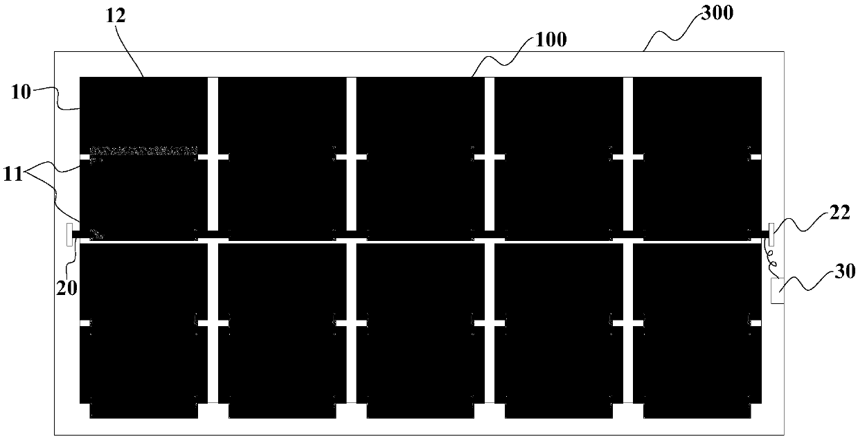
[0037] Such as figure 2 , image 3 and Figure 4 As shown, the auxiliary equipment for display substrate testing provided by the embodiment of the present invention includes a pressing roller 20 and a vacuum device 30, wherein: the pressing roller 20 is fixed above the binding area 12 of the display panel unit 10 of the display substrate 100, There are multiple vacuum suction passages 21 leading to the surface of the roller 20 ;

[0038] Optionally, the pressing rollers 20 may be...


PUM


Abstract

The present invention discloses an auxiliary device for a display substrate test and a test method of a display substrate. The auxiliary device for a display substrate test and the test method of a display substrate are able to improve the efficiency of the test for the display panel unit of the display panel and improve the design use efficiency of the display substrate. The auxiliary device for the display substrate test comprises a compaction roller and a vacuum device; the compaction roller is fixed on the binding zone of the display panel unit of the display substrate and is provided with a plurality of vacuum supply absorption channels leading to the surface of the compaction roller; and the extraction opening of the vacuum device communicates with each vacuum supply absorption channel. The auxiliary device is employed at the test of the display substrate, the FPC or PCB of the previous row / column of the display panel unit does not influence the test of the next row / column of the display panel unit, so that the efficiency of the test for the display panel unit of the display substrate is improved; and moreover, after the auxiliary device is employed, the distance between the adjacent display panel units of the display substrate is able to be small, so that the design utilization of the display substrate is improved.

Description

technical field [0001] The invention relates to the technical field of display substrate testing, in particular to an auxiliary device for display substrate testing and a display substrate testing method. Background technique [0002] Such as figure 1 As shown, the uncut display substrate 100 generally includes a plurality of display panel units 10 (ie, Q-panel), and each display panel unit 10 is bound with an FPC 11 (Flexible Printed Circuit board, flexible printed circuit board). The binding area of ​​some display panel units is bound to a PCB (Printed Circuit Board, printed circuit board). In order to prevent unqualified display panel units 10 from flowing into the next process, it is necessary to test each display panel unit 10 on the display substrate 100 . [0003] The disadvantages of the prior art are that, as figure 1 As shown, if the distance between two adjacent rows of display panel units 10 on the display substrate 100 is relatively close, the FPC 11 or PCB o...

Claims


Application Information

Patent Timeline
Patent Type & Authority Patents(China)
IPC IPC(8): G01R31/28
CPCG01R31/2808
Inventor 王泓
Owner BOE TECH GRP CO LTD
Learn More