
Headland Operation Control System

An operation control and headland technology, applied in the direction of control/adjustment system, manual control mechanism, control mechanism, etc., can solve problems such as operator fatigue, tool damage stress, unintentional failure, etc.

Active Publication Date: 2018-11-30
DEERE & CO
View PDF5 Cites 0 Cited by
  • Summary
  • Abstract
  • Description
  • Claims
  • Application Information

AI Technical Summary

Problems solved by technology

This results in operator fatigue which can lead to unintentional failure of the operator to actuate one of the switches or levers, resulting in damage to the implement and stress on the PTO shaft and implement

Method used


Image

  • Headland Operation Control System
  • Headland Operation Control System
  • Headland Operation Control System

Examples


Embodiment Construction

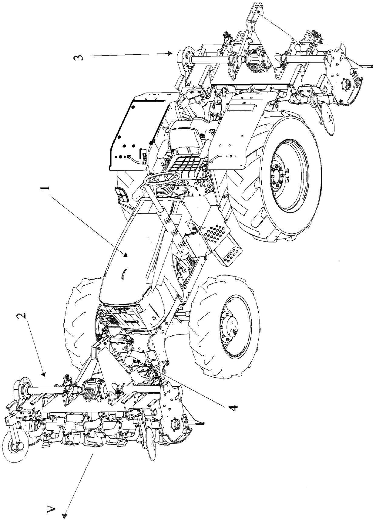
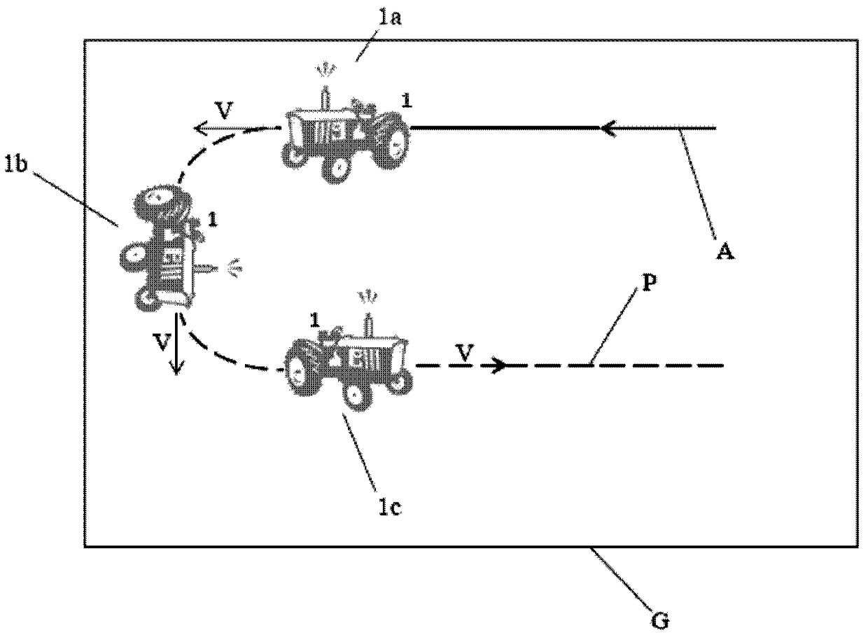
[0028] Vehicles, especially work vehicles such as tractors, need to maneuver around headlands. This requires the operator of the vehicle to perform several operations simultaneously, such as disengaging power to the power take-off (PTO) shaft, disengaging the four-wheel drive, and raising the implement through the tractor's lift arm. Operating multiple mechanisms simultaneously causes operator stress and fatigue. The present invention contemplates operating a single system to operate multiple mechanisms of the vehicle. The headland operation control system of the present invention can be retrofitted to the existing system of the vehicle.

[0029] Embodiments herein and their various features and advantageous details are described with reference to the non-limiting examples described hereinafter. Descriptions of well-known components and processing techniques are omitted so as not to unnecessarily obscure the embodiments herein.

[0030] see figure 1 , the tractor 1 is illu...


PUM


Abstract

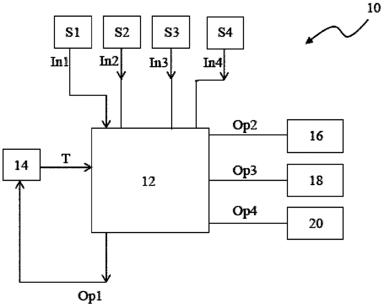
The invention discloses a field edge operation control system (10) for controlled operation of a plurality of mechanisms (16, 18, 20) related to a vehicle. The field edge operation control system (10) comprises a controller (12) configured to process input signals (In1, In2, In3 and In4), and the input signals (In1, In2, In3 and In4) are from a speed measurement device (S1) detecting a predetermined minimum ground speed and sensors (S2, S3 and S4) associated with the corresponding mechanisms. When a vehicle ground speed is detected to be greater than the predetermined minimum ground speed, the controller triggers an actuating component (14) to be capbel of moving from a working position to a non-working position. According to the non-working position and the working position of the actuating component (14), the controller (12) processes the signals (In2, In3 and In4) from the sensors (S2, S3 and S4) and then generates output signals (Op2, Op3, Op4) to trigger desired operation of the mechanisms (16, 18, 20).

Description

technical field [0001] The present invention relates to the field of controlled operation of mechanisms associated with vehicles. Background technique [0002] Vehicles, especially work vehicles such as tractors, used to provide traction for the operation of various implements. These implements may be connected to the tractor via a PTO shaft and hitch, or just the hitch. A power take-off (PTO) shaft is operated or turned by utilizing power from the work vehicle. The PTO enables power to be transmitted from the work vehicle to operate at least one implement or other agricultural machinery. These implements and machinery are used to perform several operations such as preparing the land for tillage, harvesting crops, leveling the land, etc. [0003] However, it is preferred that the operation of the PTO is turned off when the work vehicle needs to maneuver over an arriving headland or headland. Conventionally, the operator of the work vehicle needs to turn off power to the ...

Claims


Application Information

Patent Timeline
Patent Type & Authority Patents(China)
IPC IPC(8): G05G9/00
CPCA01B69/008
Inventor 古卜达·绍拉伯南纳吉卡尔·维韦卡
Owner DEERE & CO
Learn More