Rope traction robot applied to transportation and assembly of space materials

A technology of robots and traction mechanisms, applied in transportation and packaging, aerospace vehicles, manipulators, etc., can solve the problems of limited transfer distance and low transportation efficiency, and achieve the effect of small construction difficulty, fast moving speed and simple structure

Pending Publication Date: 2022-05-06
HARBIN INST OF TECH
View PDF0 Cites 0 Cited by
  • Summary
  • Abstract
  • Description
  • Claims
  • Application Information

AI Technical Summary

Problems solved by technology

[0006] The purpose of the present invention is to solve the problems of limited transfer distance and low transportation efficiency in existing space material transportation and assembly devices

Method used


Image

  • Rope traction robot applied to transportation and assembly of space materials
  • Rope traction robot applied to transportation and assembly of space materials

Examples


specific Embodiment approach 1

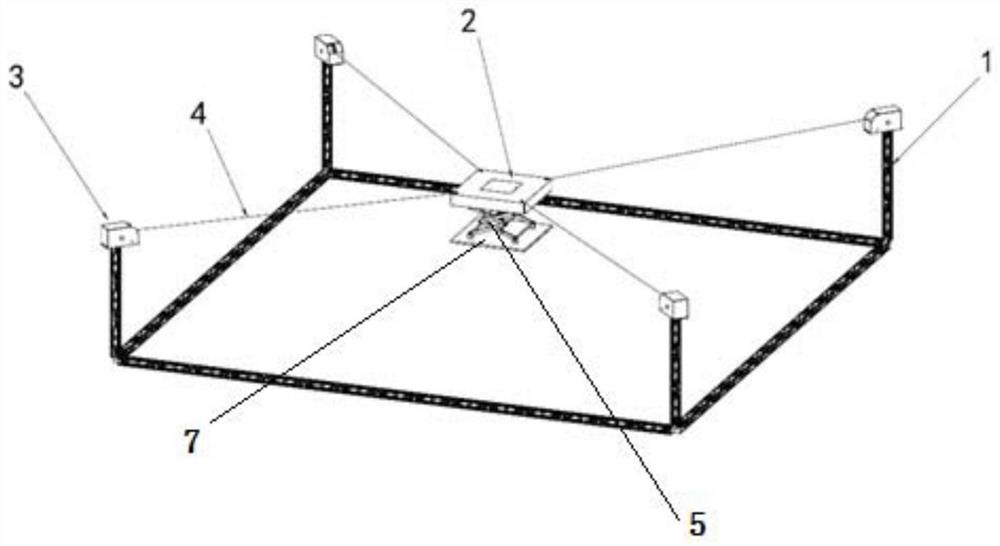
[0013] Specific implementation mode one: combine Figure 1 to Figure 2 Describe this embodiment. A rope traction robot applied to the transportation and assembly of space materials in this embodiment includes a support structure 1, a mobile base 2, a plurality of traction mechanisms 3, a plurality of traction ropes 4, a lifting mechanism 5, and a docking and clamping mechanism. The mechanism 6 and the bottom plate 7, the support structure 1 is a frame structure, the support structure 1 is arranged in the space of weightlessness in space, a traction mechanism 3 is installed at least three points on the support structure 1 that are not located on the same straight line, and each traction rope One end of 4 is connected to a traction mechanism 3, and the other end of each traction rope 4 is connected to the mobile base 2 located in the middle of the support structure 1. Multiple traction ropes 4 drive the mobile base 2 to move under the action of the traction mechanism 3, and the l...

specific Embodiment approach 2

[0017] Specific implementation mode two: combination figure 1 To describe this embodiment, the traction rope 4 of this embodiment is a steel wire rope or a cable with a conductive function. Such setting facilitates power transmission for the robot base and other equipment through the traction rope 4 . Other compositions and connections are the same as in the first embodiment.

[0018] The traction rope 4 of this embodiment can realize power transmission between the robot base 2 and the supporting structure 1 .

specific Embodiment approach 3

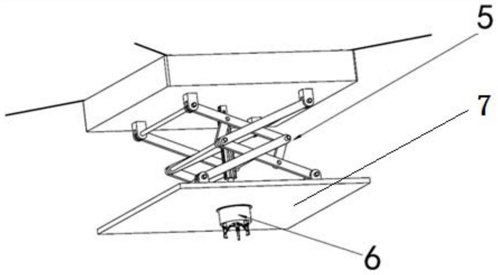
[0019] Specific implementation mode three: combination Figure 1 to Figure 2 Describe this embodiment, this embodiment also includes a docking clamping mechanism 6, the docking clamping mechanism 6 is installed on the lower end surface of the bottom plate 7, and the docking clamping mechanism 6 clamps the assembly robot. So set up to hold robots with precision butt fittings. Other compositions and connections are the same as those in Embodiment 1 or Embodiment 2.


PUM


Abstract

The invention relates to a rope traction robot, in particular to a rope traction robot applied to space material transportation and assembly. The problems that an existing space material transporting and assembling device is limited in transferring distance and low in transporting efficiency are solved. A supporting structure (1) is of a frame structure, the supporting structure (1) is arranged in a space weightless in the space, at least three points, not located on the same straight line, of the supporting structure (1) are each provided with a traction mechanism (3), one end of each traction rope (4) is connected with the corresponding traction mechanism (3), and the other end of each traction rope (4) is connected with a movable base (2) located in the middle of the supporting structure (1). The multiple traction ropes (4) drive the movable base (2) to move under the action of the traction mechanism (3), and the lower end face of the movable base (2) is provided with the robot through the lifting mechanism and the butt-joint clamping mechanism to achieve transportation and assembly of goods and materials. The invention is used for space material transportation and assembly.

Description

technical field [0001] The invention relates to a rope traction robot, in particular to a rope traction robot applied to the transportation and assembly of space materials. Background technique [0002] At present, almost all spacecraft are manufactured and verified on the ground, and then sent to a predetermined orbit by a launch vehicle. With the continuous improvement of space exploration requirements, the contradiction between the rapidly increasing size of spacecraft and the slowly increasing volume and weight of launch vehicle payloads has become increasingly prominent. Large-scale deployable mechanisms are an effective way to solve the above-mentioned contradictions, but the deployment caliber, weight and mechanical properties still cannot meet the development needs of large or ultra-large space structures in the future. Therefore, the construction concept based on "modular deployable mechanism + on-orbit assembly" has become a technical consensus in the design and c...

Claims


Application Information

Patent Timeline
IPC IPC(8): B64G1/22B25J11/00
CPCB64G1/22B64G1/222B25J11/00
Inventor 郭闯强刘谊孙永军刘宏
Owner HARBIN INST OF TECH
Why Eureka
Try Eureka