
Online adjustable exciting vibration equipment

An adjustment type, vibration excitation technology, applied in the direction of fluid using vibration, can solve the problems of complex excitation force adjustment, inability to adjust, affecting work efficiency, etc., to achieve low noise, good sealing, and improve work efficiency. Effect

Active Publication Date: 2012-02-08
BIRTLEY TIANJIN IND EQUIP
View PDF5 Cites 12 Cited by
  • Summary
  • Abstract
  • Description
  • Claims
  • Application Information

AI Technical Summary

Problems solved by technology

[0002] Nowadays, vibration equipment is widely used in various industries such as coal, electric power, docks, foundries, chemical plants, etc. At the same time, the requirements for vibration equipment in various industries are becoming increasingly stringent, and the size and frequency of the required excitation force are also increasingly diverse. , Nowadays, most vibration equipment uses vibration motors. Most of the market uses vibration motors to work, and vibration motors can only provide a certain value of excitation force at a time, and cannot achieve the purpose of adjustment during work. If you want to adjust its excitation force It is very inconvenient to adjust the size and size of the equipment that has different requirements for the excitation force and frequency at different times, and it lacks certain accuracy, which seriously affects the work efficiency. The adjustment of the exciting force becomes more complicated in high altitude, airtight and other environments where assembly and disassembly are inconvenient

Method used


Image

  • Online adjustable exciting vibration equipment
  • Online adjustable exciting vibration equipment
  • Online adjustable exciting vibration equipment

Examples


Embodiment Construction

[0013] Embodiments of the present invention are further described below in conjunction with accompanying drawings:

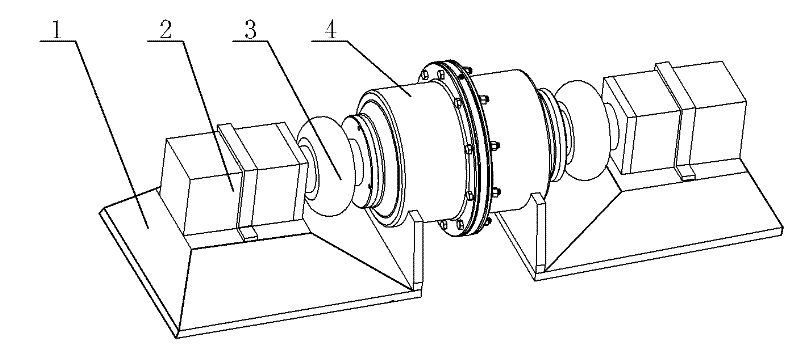
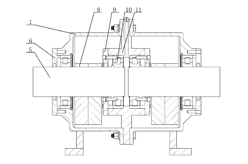
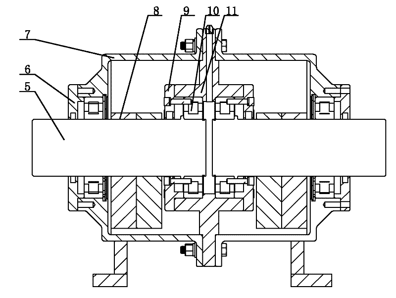
[0014] Such as figure 1 , 2 As shown, the online adjustable vibration excitation equipment includes an installation platform 1, a vibration exciter 4 and a servo motor 2 controlled by a PLC control system. The specific structure of the vibration exciter 4 includes a short shaft 5, an end cover 6, and a casing 7 , eccentric block 8, gland 9, bearing 10 and bearing seat 11, the shell of the exciter 4 is formed by connecting two left and right symmetrical casings 7, the bearing seat 11 is assembled in the inner hole of the casing 7 and the casing 7 and the bearing seat 11 are positioned by a notch, and the bearing seat 11 is provided with a lubricating device. The two short shafts 5 provided in the vibrator 4 are left and right symmetrical and coaxial, and the eccentric block 8 is fixed on the short shaft 5, and the two short shafts 5 are respectively connected t...


PUM


Abstract

The invention relates to online adjustable exciting vibration equipment, which is applied to equipment which requires variable exciting force such as a vibration sieve, an activation feeder and the like. The equipment comprises an installation platform, a vibration exciter and servo motors, wherein the servo motors re controlled by a PLC (Programmable Logical controller) control system; two shortshafts which are bilaterally symmetrical and coaxial with each other are arranged in the vibration exciter; eccentric blocks are fixed on the short shafts; the two short shafts are connected with corresponding servo motors through shaft couplings respectively; and the servo motors are fixed on the installation platform. The entire set of equipment runs stably and has low noise; an include angle can be formed between the two eccentric blocks by controlling the phase angles of two servo motor shafts; the frequency and the magnitude of the exciting force can be adjusted conveniently without halting, so that the working efficiency is greatly increased, and the requirements of different exciting forces on different occasions can be met; due to the adoption of the PLC control system, adjustmentis more accurate and reliable; the vibration exciter has high internal airtightness, is flexible for disassembling and assembling, and is convenient for maintaining; and a plurality of installation and positioning ways are adopted for the vibration exciter, so that the concentricity of the two eccentric blocks is fully ensured.

Description

technical field [0001] The invention relates to an on-line adjustable vibration excitation device, which is applied to vibration screens, activation feeders and other equipment that need to provide variable excitation force. Background technique [0002] Nowadays, vibration equipment is widely used in various industries such as coal, electric power, docks, foundries, chemical plants, etc. At the same time, the requirements for vibration equipment in various industries are becoming increasingly stringent, and the size and frequency of the required excitation force are also increasingly diverse. , Nowadays, most vibration equipment uses vibration motors. Most of the market uses vibration motors to work, and vibration motors can only provide a certain value of excitation force at a time, and cannot achieve the purpose of adjustment during work. If you want to adjust its excitation force It is very inconvenient to adjust the size and size of the equipment that has different requ...

Claims


Application Information

Patent Timeline
IPC IPC(8): B06B1/16
Inventor 陈兵刘淑良侯波
Owner BIRTLEY TIANJIN IND EQUIP
Learn More