
Automatic steel casing cutting device with positioning function

An iron-shell, automatic technology, applied in metal processing and other directions, can solve the problems of enterprise loss, loss, and movement of the carrier plate, and achieve the effect of improving processing quality, improving stability and running smoothly.

Inactive Publication Date: 2014-04-30
KUNSHAN FOR EASIER AUTOMATION TECH
View PDF0 Cites 13 Cited by
  • Summary
  • Abstract
  • Description
  • Claims
  • Application Information

AI Technical Summary

Problems solved by technology

However, due to the long iron shell material belt, there are superimposed parts when the two material belts are connected. When conveying the material belt, the superimposed part on the material belt cannot pass through the flow channel, resulting in material jamming, affecting the overall conveying of the material belt, and When cutting the iron shell later, it is very easy to cut the shell, causing unnecessary losses
At the same time, the wire harness needs to be installed on the corresponding connector iron shell during processing. In this way, the connector iron shell must be cut from the material tape, and the iron shell is cut from the material tape. The cutting accuracy requirements It is very high, and it is necessary to keep the iron shell in a relatively stable state, otherwise the cutting position is prone to shift, resulting in damage to the cut product. At the same time, the current material belt feeding mechanism is a single mechanism. After being combined with the positioning mechanism, the entire equipment will be damaged. complex structure
In addition, in cutting the iron shell of the connector, due to the large processing range of the equipment, this often causes the carrier board to move accordingly, which affects the processing accuracy of the product, resulting in a large number of defective products, which brings great harm to the enterprise. big loss

Method used


Image

  • Automatic steel casing cutting device with positioning function
  • Automatic steel casing cutting device with positioning function
  • Automatic steel casing cutting device with positioning function

Examples


Embodiment Construction

[0028] The present invention will be further described below in conjunction with the accompanying drawings.

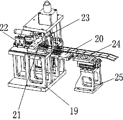
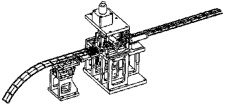
[0029] Such as Figure 1-2 As shown, an automatic iron case cutting device with a positioning function includes a workbench 19, a carrier plate 20, a material shifting mechanism 21, a stacking induction mechanism 22 and a cutting mechanism 23, and the workbench 19 is provided with a The slideway with feeding, at the rear of the workbench 19, a stacking induction mechanism 22 is arranged above the iron shell material belt 24, and a material shifting mechanism 21 that drives the material belt to advance is provided at the front end of the stacking sensing mechanism 22. A cutting mechanism 23 is arranged at the front end of the mechanism 21 , and a carrier plate 20 is arranged beside the cutting mechanism 23 .

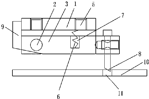
[0030] Such as Figure 3-4 As shown, the material shifting mechanism 21 of the present invention includes a fixed block 1, a pin shaft 2, a rotating plate 3, a ...


PUM


Abstract

The invention discloses an automatic steel casing cutting device with a positioning function. The automatic steel casing cutting device with the positioning function comprises a work table and a carrier plate, and is characterized by further comprising a material stirring mechanism, a material overlapping induction mechanism, a cutting mechanism and a position limiting mechanism, wherein a slide rail used for material feeding of a steel casing material belt is arranged on the work table, the material overlapping induction mechanism is arranged at the rear of the work table and above the steel casing material belt, the material stirring mechanism which drives the steel casing material belt to advance is arranged at the front end of the material overlapping induction mechanism, the cutting mechanism is arranged at the front end of the material stirring mechanism, and the carrier plate is arranged beside the cutting mechanism. The automatic steel casing cutting device with the positioning function is simple in structure, convenient to use, high in machining precision and convenient in material feeding, can rapidly locate the material belt and the carrier plate, and facilitates induction of material overlapping of the material belt, and then can send an alarm.

Description

technical field [0001] The invention relates to a connector iron shell processing device, in particular to an automatic iron shell cutting device with a positioning function. Background technique [0002] The wiring harness is a wiring component that connects various electrical equipment in the circuit, and is composed of core wires, insulation, braiding, and sheathing. The quality of the wiring harness is directly related to whether the entire electrical equipment can work normally and safely. When processing the wire harness, the wire harness needs to be installed on the corresponding connector iron shell, so the connector iron shell must be cut off from the material tape. However, due to the long iron shell material belt, there are superimposed parts when the two material belts are connected. When conveying the material belt, the superimposed part on the material belt cannot pass through the flow channel, resulting in material jamming, affecting the overall conveying of ...

Claims


Application Information

Patent Timeline
IPC IPC(8): B23D79/00B23Q7/00
Inventor 操林郭池洪曹洪胜
Owner KUNSHAN FOR EASIER AUTOMATION TECH
Learn More