Cell for gas generation

Inactive Publication Date: 2005-09-22
PERMA TEC
View PDF4 Cites 1 Cited by
  • Summary
  • Abstract
  • Description
  • Claims
  • Application Information

AI Technical Summary

Benefits of technology

[0012] The electrolyte fluid can have an anti-freeze agent added to it, which preferably is made up of ethylene glycol and/or dimethyl sulfoxide. In this way, proper operation of the gas cell is guaranteed even at low temperatures. To prevent a hydrogen over-voltage of the electrode forming the cathode, the electrolyte fluid can

Problems solved by technology

Usual buffer substances, e.g. phosphates, are unsuitable for s

Method used


Image

  • Cell for gas generation
  • Cell for gas generation
  • Cell for gas generation

Examples


Example

EXAMPLE

[0021] The following electrolyte fluids were produced: [0022] a) 15.0 g sodium azide, [0023] 31.0 g magnesium perchlorate, content 83 wt.-%, aqueous, [0024] 100 ml water. [0025] b) Composition as in a), but with the addition of 0.25 g nickel sulfate*6 H2O.

[0026] The magnesium perchlorate binds the soda lye that is formed during the reaction, by forming magnesium hydroxide that has low solubility. This magnesium hydroxide is precipitated as a precipitate and is thereby withdrawn from the reaction equilibrium.

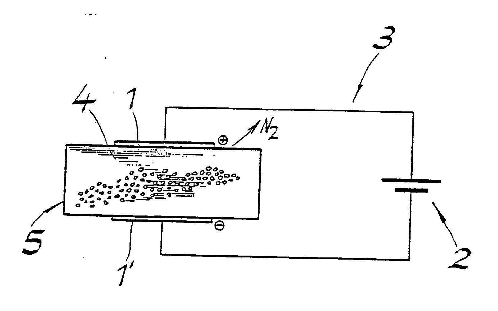
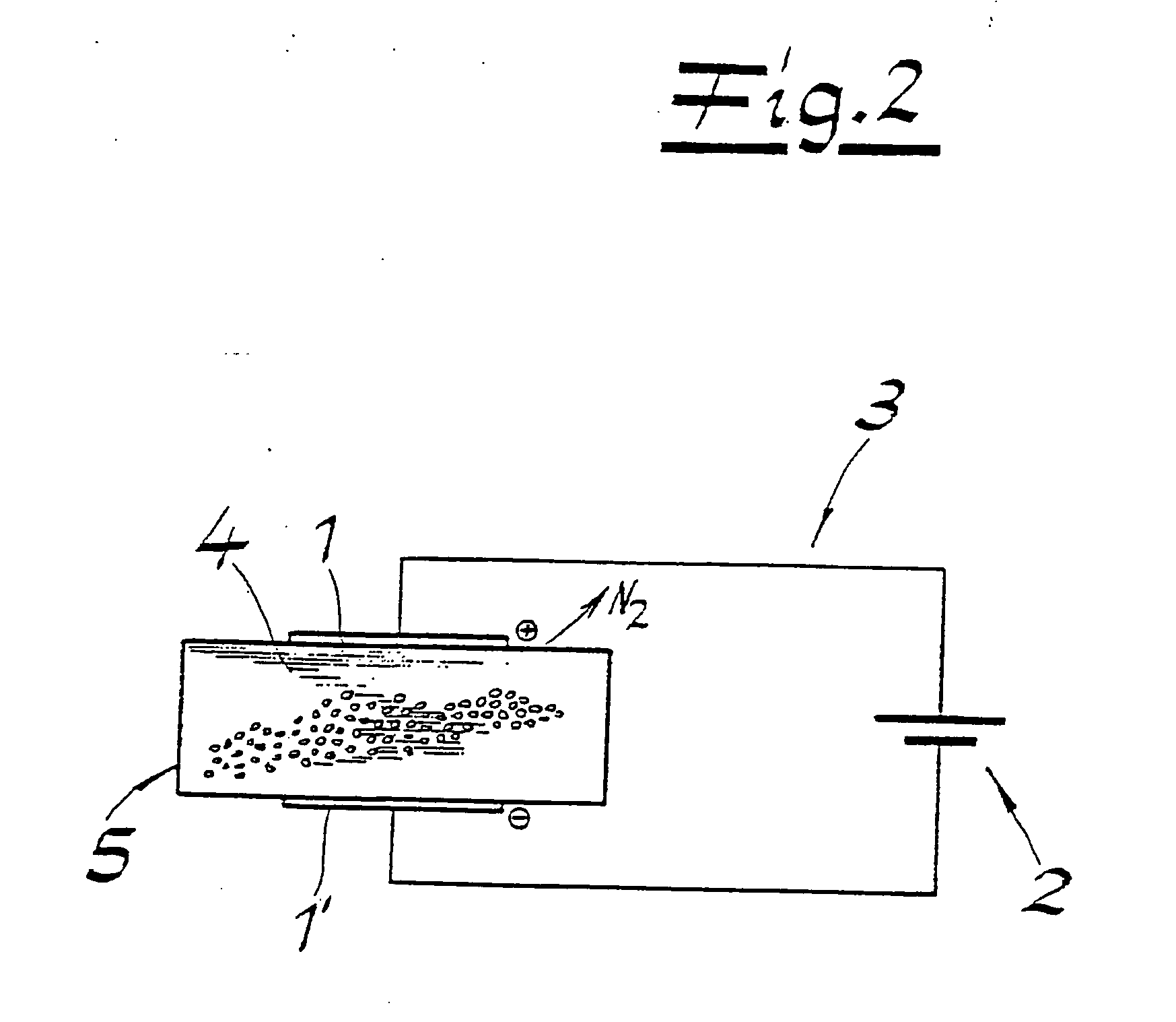
[0027] The use of magnesium perchlorate has the advantage that the electrolyte fluid remains liquid to below −20° C. As a result, anti-freeze agents need not be added, and the electrolyte fluid can easily be absorbed in a sponge. In this way, a simple separation of gas and electrolyte fluid, independent of the position, is present in practical operation. The disposal of a cell that contains the electrolyte fluid (see FIG. 2) can take place by means of incineration. The ...


PUM

PropertyMeasurementUnit
Electric potential / voltageaaaaaaaaaa
Freezing pointaaaaaaaaaa

Abstract

A cell for gas generation is provided, particularly for the operation of a lubricant dispenser. The cell has two electrodes to be connected to a circuit containing a power source, and an aqueous electrolyte fluid located between the two electrodes, containing an azide having the formula XN3, for electrochemical generation of a gas containing nitrogen (N2). The electrolyte fluid contains a magnesium salt as an additive, for chemical binding of hydroxide ions that are formed during the electrochemical reaction.

Description

CROSS REFERENCE TO RELATED APPLICATIONS [0001] Applicants claim priority under 35 U.S.C. §119 of German Application No. 10 2004 013 593.2 filed Mar. 19, 2004 and German Application No. 10 2004 032 260.0 filed Jul. 3, 2004. BACKGROUND OF THE INVENTION [0002] 1. Field of the Invention [0003] The present invention relates to a cell for gas generation, particularly for the operation of a lubricant dispenser, having two electrodes to be connected to a circuit containing a power source, and an aqueous electrolyte fluid located between the two electrodes, containing an azide having the formula XN3, for electrochemical generation of a gas containing nitrogen (N2). [0004] 2. The Prior Art [0005] In practice, it is known to meter the amount of lubricant that is dispensed by a lubricant dispenser by means of a gas-generating cell, whereby the pressure produced using the gas causes a corresponding exit of lubricant from the dispenser. In this connection, the generation of hydrogen or oxygen at ...

Claims


Application Information

Patent Timeline
IPC IPC(8): C25B1/00C25B9/00
CPCC25B1/00A44B19/265A45B25/18
Inventor GRAF, WALTERWEIGAND, MICHAELGLIER, ROBERTGLIER, RENATE
Owner PERMA TEC
Why Eureka
Try Eureka