
Microgrid system and operation control method of the microgrid system

A micro-grid and controller technology, applied in the direction of single-grid parallel feeding arrangement, transportation and packaging, DC network circuit devices, etc., can solve the problem of the micro-grid system being unable to load power supply, etc. less effect

Active Publication Date: 2019-12-20
BYD CO LTD
View PDF1 Cites 0 Cited by
  • Summary
  • Abstract
  • Description
  • Claims
  • Application Information

AI Technical Summary

Problems solved by technology

[0003] In the related art, a DC micro-grid system that is connected to the grid and not connected to the grid is proposed. The DC / AC conversion device connected to the DC bus provides energy for the load in this micro-grid system. The disadvantage is that the power required by the load is completely Determined by the DC / AC conversion device, when the load power is greater than the rated output power of the DC / AC conversion device, the microgrid system will not be able to supply power to the load

Method used


Image

  • Microgrid system and operation control method of the microgrid system
  • Microgrid system and operation control method of the microgrid system
  • Microgrid system and operation control method of the microgrid system

Examples


Embodiment Construction

[0015] Embodiments of the present invention are described in detail below, examples of which are shown in the drawings, wherein the same or similar reference numerals designate the same or similar elements or elements having the same or similar functions throughout. The embodiments described below by referring to the figures are exemplary and are intended to explain the present invention and should not be construed as limiting the present invention.

[0016] The microgrid system and the operation control method of the microgrid system according to the embodiments of the present invention will be described in detail below with reference to the accompanying drawings.

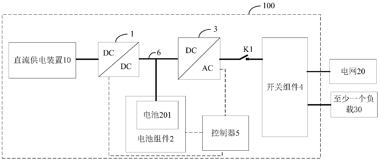
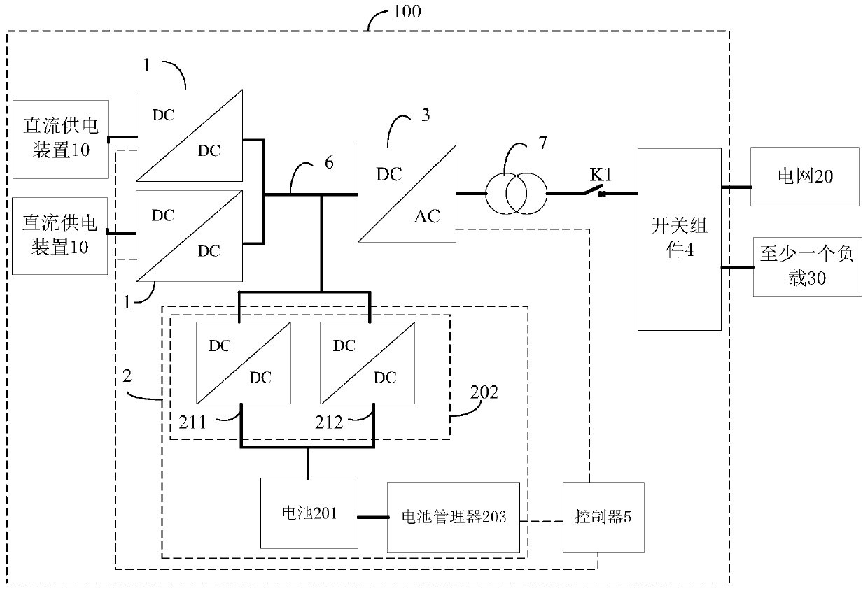
[0017] figure 1 is a schematic block diagram of a microgrid system according to an embodiment of the present invention. Such as figure 1 As shown, the microgrid system 100 includes: a DC power supply device 10 , a first DC / DC conversion device 1 , a battery assembly 2 , a bidirectional converter device 3 , a swi...


PUM


Abstract

The present invention discloses a micro-grid system which comprises a DC power supply device, a first DC / DC conversion device, a battery component comprising a battery, a double-direction converting device, a switch component which is provided with multiple switches and is used for selecting a part of switches in the multiple switches to be turned on according to the command of a user, a first switch which is connected between the double-direction converting device and the switch component, and a controller which is used for controlling the operation mode of the micro-grid system according to the turn-on and turn-off states of the switch component and the first switch, wherein the operation mode of the micro-grid system is a grid-connected mode, the double-direction converting device is used for obtaining the current power of a grid and controlling the output power of the double-direction converting device according to the difference between a preset power and the current power of the grid and a preset PI control mode. The micro-grid system allows a load to run in a grid-connected / grid-off mode, the grid makes up power for the load when the system output power is not enough, and the micro-grid system is prevented from injecting electric energy into the grid. The invention also discloses a control method of a micro-grid system.

Description

technical field [0001] The invention relates to the technical field of power electronics, in particular to a microgrid system and an operation control method for the microgrid system. Background technique [0002] With the development of green energy, various forms of energy storage power stations have also begun to be promoted. Due to the limitation of site and operating costs, it is impossible to meet the growing energy demand only by relying on large-scale energy storage power stations, and the relatively convenient and flexible micro-grid system has broad development prospects. The microgrid system may include an online microgrid system and a non-internet microgrid system. Among them, the on-grid microgrid system is connected to the grid, and can operate in the mode of peak shaving and valley filling, photovoltaic smoothing, etc., allowing the microgrid system to inject energy into the grid; the off-grid microgrid system can be connected to the grid, or it can be indepe...

Claims


Application Information

Patent Timeline
Patent Type & Authority Patents(China)
IPC IPC(8): H02J1/00H02J7/34H02J3/38
Inventor 尹韶文孙嘉品杨荣春
Owner BYD CO LTD
Learn More