Ventilation device inside the helmet

A technology for ventilating device and helmet, which is applied to helmets, helmet caps, headgear products, etc., can solve the problems that the cross-sectional area of ​​the introduction pipe cannot be too large, the air cannot be fed into the helmet, and the head sultry cannot be fully eliminated. Head sultry effect

Active Publication Date: 2018-07-20
SEFT DEVMENT LAB
View PDF6 Cites 0 Cited by
  • Summary
  • Abstract
  • Description
  • Claims
  • Application Information

AI Technical Summary

Problems solved by technology

First, since the unit mounts directly to the helmet, it is not possible to use a unit with an excessively heavy blower
Therefore, it is not possible to send a large amount of air into the helmet to sufficiently eliminate head stuffiness
Second, since the introduction pipe is arranged in the gap between the helmet and the head, the cross-sectional area of ​​the introduction pipe cannot be too large
The work helmet with the air blowing function also has the same problems as the above-mentioned device in terms of air volume and power consumption.

Method used


Image

  • Ventilation device inside the helmet
  • Ventilation device inside the helmet
  • Ventilation device inside the helmet

Examples


no. 1 approach

[0025] Next, a helmet ventilation device as a first embodiment of the present invention will be described.

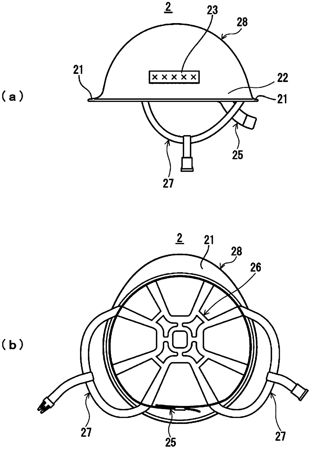
[0026] figure 2 (a) is a schematic front view when the helmet ventilation device according to the first embodiment of the present invention is deployed, figure 2 (b) is a schematic rear view of the ventilation device in the helmet. In addition, in figure 2 , which depicts the state when the expansion and contraction part of the ventilator in the helmet is stretched to the maximum.

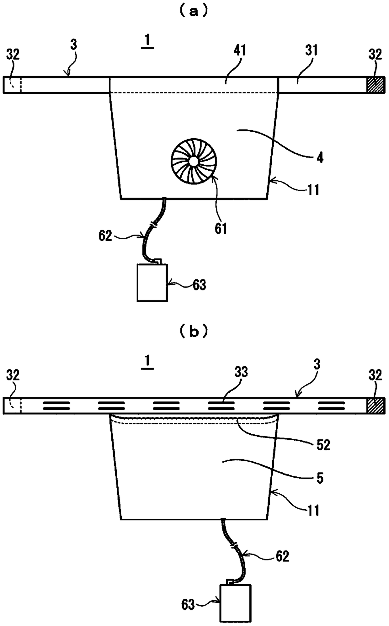
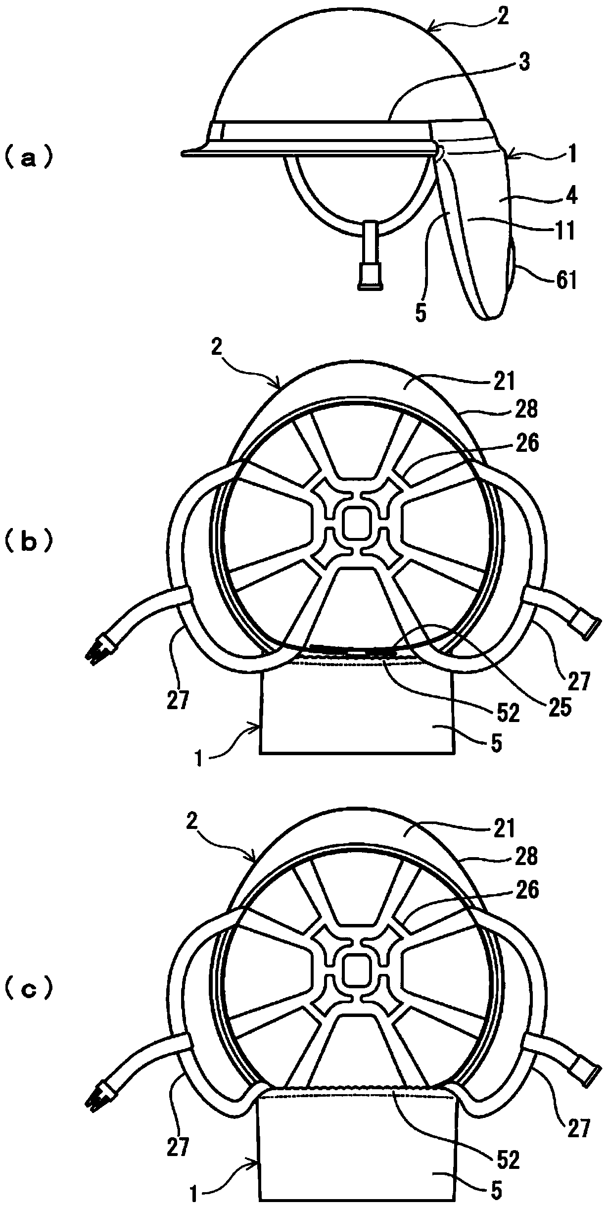
[0027] The ventilation device in the helmet of the first embodiment is mounted on the helmet 2 for use. Such as figure 2 As shown, the ventilation device 1 in the helmet has: a bag-shaped body 11 made of cloth, a mounting belt (mounting unit) 3, an air blowing unit 61, a power supply (power supply unit) 63 for driving the air blowing unit 61, and the The air blowing unit 61 is electrically connected to a power supply 63 with a cable 62 .

[0028] The bag-shaped body 11 is formed in...

no. 2 approach

[0061] Next, a helmet-mounted ventilator as a second embodiment of the present invention will be described. The helmet inner ventilation panel 1a of the second embodiment is mainly used in hot weather. Figure 8 (a) is a schematic front view of a first guide piece used in a helmet interior ventilation device according to a second embodiment of the present invention, Figure 8 (b) a schematic front view of the second guide piece used by the ventilation device in the helmet, Figure 8 (c) is a schematic rear view of the bag-shaped body of the ventilation device in the helmet, Figure 8 (d) is a schematic front view of the ventilation device in the helmet. Here, above Figure 8 (a), Figure 8 (b), Figure 8 (c), Figure 8 (d) is respectively the same as in the first embodiment Figure 7 (a), Figure 7 (b), Figure 7 (c), Figure 7 (d) Corresponding figure. Thus, in Figure 8 (c) and Figure 8 (d) depicts the state when the stretchable part 52 of the bag-like body 11a...


PUM


Abstract

A ventilating device in a helmet which can sufficiently solve sweatiness of the head part of a user when the helmet is worn is provided. The ventilating device 1 in a helmet of the present invention includes a bag-shaped body 11 formed having a shape of a bag with an upper part open by using a first guiding sheet 4 and a second guiding sheet 5, attaching means 3 provided on an upper end portion of the first guiding sheet for attaching the bag-shaped body to the helmet 2, air blowing means 61 attached to a lower part of the bag-shaped body 11 for taking in outside air into the bag-shaped body and sending it out to a side of an open portion of the bag-shaped body along the first guiding sheet and the second guiding sheet, and power supply means for driving the air blowing means. The air having been taken into the bag-shaped body 11 by the air blowing means 61 is introduced into the helmet 2 through an air inlet formed between an inner edge of the helmet 2 and the head part of the user so as to ventilate the inside of the helmet 2.

Description

technical field [0001] The present invention relates to a ventilator in a helmet for ventilating the interior of the helmet by sending air into the helmet when the helmet is worn. Background technique [0002] In recent years, devices for adding an air blowing function to conventional work helmets satisfying safety standards have been put into practical use (for example, refer to Patent Document 1). The above device is configured such that a blower is attached to the outer edge of the helmet, and external air sucked by the blower is sent into the helmet through an introduction pipe (for example, a tubular duct). [0003] Patent Document 1: Japanese Unexamined Patent Publication No. 2012-180606 [0004] However, in the device for adding the air blowing function to the above-mentioned work helmet, there are serious problems in performance as follows. First, since the device is mounted directly to the helmet, it is not possible to use a device with an excessively heavy blower...

Claims


Application Information

Patent Timeline
Patent Type & Authority Patents(China)
IPC IPC(8): A42B3/28
CPCA42B3/286
Inventor 市谷弘司
Owner SEFT DEVMENT LAB
Why Eureka
Try Eureka