Button cell terminal

A battery and button technology, which is applied to battery pack components, battery boxes/coats, small-sized batteries/battery packs, etc., can solve problems such as poor conduction, easy plastic deformation, and shortened product life.

Active Publication Date: 2016-06-22
DENSO CORP
View PDF7 Cites 1 Cited by
  • Summary
  • Abstract
  • Description
  • Claims
  • Application Information

AI Technical Summary

Problems solved by technology

[0004] Since the battery insertion direction is opposite to the deformation load direction in the structure of the button battery terminal (the two vectors are perpendicular to each other), plastic deformation is likely to occur, and conduction failure will occur when plastic deformation occurs
In addition, although there are terminals of

Method used


Image

  • Button cell terminal
  • Button cell terminal
  • Button cell terminal

Examples


Embodiment Construction

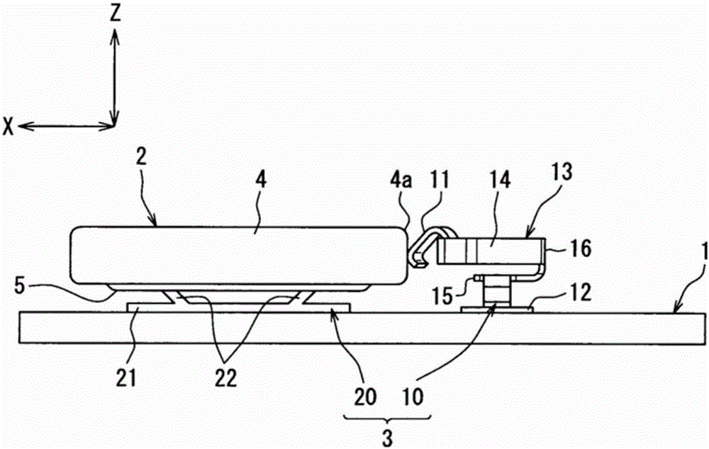
[0014] Hereinafter, one embodiment of the terminal for a coin-type battery according to the present disclosure will be described with reference to the drawings. Among them, the button-type battery terminal of this embodiment is applied, for example, to electrical equipment such as a wireless transmitter for vehicles that wirelessly transmits a signal for operating a door lock device of a vehicle to a receiver mounted on a vehicle. Electrically connected to the circuit board.

[0015] like figure 1 As shown, in a case (not shown) constituting an electric device, a circuit board 1 on which various electric components of an electronic component unit are mounted is accommodated. On the mounting surface of the circuit board 1 are mounted an IC (Integrated Circuit) not shown that controls the operation of the electric device, a battery terminal 3 that holds a button battery 2 as a power source of the electric device in an electrically connected state, and the like.

[0016] The b...


PUM


Abstract

A button cell terminal (10) electrically connecting a button cell (2) and a circuit board (1) is provided with spring contact terminal portions (11), board bonding portions (12), and a pressure-absorbing spring portion (13). The spring contact terminal portions are formed in a spring shape deforming elastically in response to pressure in the X-axis direction and the Z-axis direction from the button cell. The board bonding portions are bonded to the circuit board. The pressure-absorbing spring portion is provided with a bending arm portion (14) for absorbing pressure from the button cell by elastic deformation in response to pressure in the X-axis direction and the Y-axis direction from the button cell.

Description

technical field [0001] This indication is based on the Japanese patent application number 2013-232897 for which it applied on November 11, 2013, and uses the description content here. [0002] This disclosure relates to a terminal for a coin-type battery that electrically connects a coin-type battery to a circuit board. Background technique [0003] Conventionally, electric equipment such as a wireless transmitter for vehicles using a button battery as a driving source is provided with a button battery terminal electrically connecting the button battery to a circuit board as disclosed in Patent Document 1, for example. In order to define the positional relationship between the coin-type battery and the terminal, it has been proposed to mount the battery holder on the circuit board. However, in this configuration, the wiring diagram is restricted due to the mounting shape of the battery holder. Among them, although there are terminals of a type that does not require a batter...

Claims


Application Information

Patent Timeline
IPC IPC(8): H01M2/10H01M2/20H01M50/202H01M50/284H01M50/50H01M50/559
CPCY02E60/10H01M50/216H01M50/50H01M50/559H01M50/284H01M50/202H01M50/543H01R11/281H01R12/57
Inventor 今村光
Owner DENSO CORP
Why Eureka
Try Eureka