Special tools for grinding primary sun gear bushings

A special tool and sun gear technology, applied in the field of mechanical processing, can solve problems such as low lamination rate and unstable transmission, and achieve the effects of low manufacturing cost, reduced grinding workload, and convenient and quick use

Active Publication Date: 2017-10-24
HARBIN TURBINE +1
View PDF10 Cites 0 Cited by
  • Summary
  • Abstract
  • Description
  • Claims
  • Application Information

AI Technical Summary

Problems solved by technology

[0004] In the process of meshing the first-stage sun gear sleeve and the sun gear in the existing steam turbine reducer, the bonding rate is not high, which leads to the problem of unstable transmission, and then it is proposed to grind the first-stage sun gear sleeve special tool for

Method used


Image

  • Special tools for grinding primary sun gear bushings
  • Special tools for grinding primary sun gear bushings
  • Special tools for grinding primary sun gear bushings

Examples


specific Embodiment approach 1

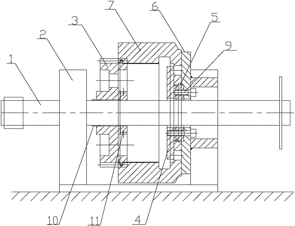
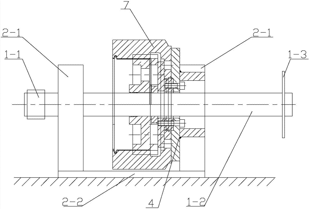
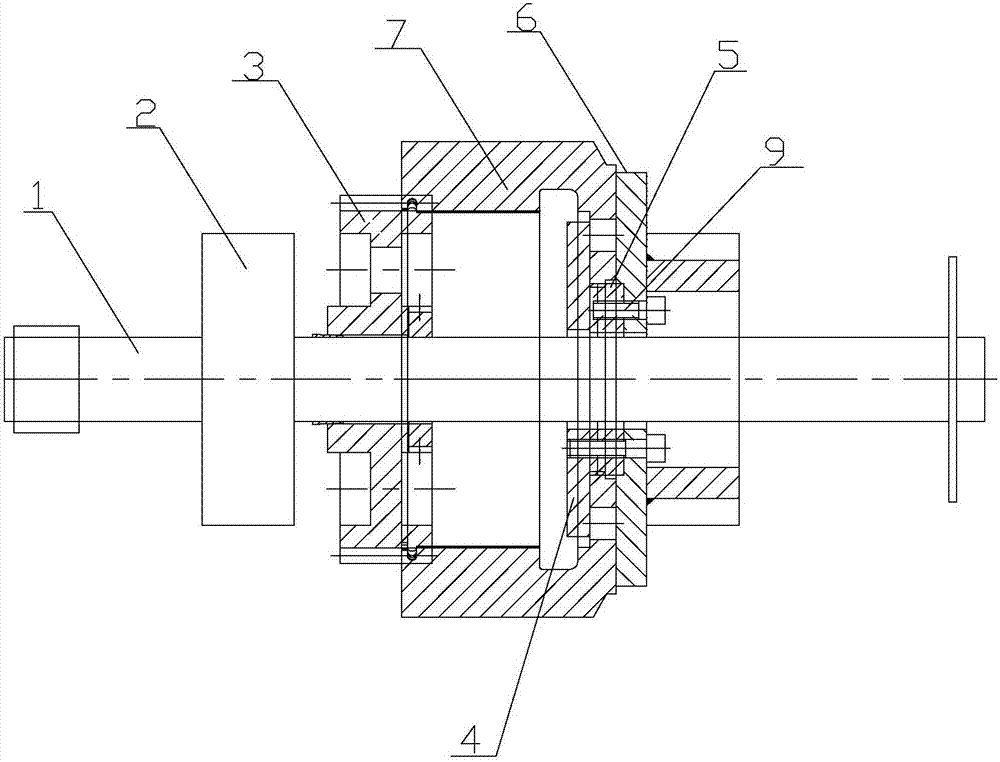
[0017] Specific implementation mode one: combine figure 1 , figure 2 , image 3 , Figure 4 , Figure 5 , Image 6 with Figure 7 Describe this embodiment, this embodiment includes pull rod 1, support frame 2, grinding gear 3, tightening flange 4, positioning flange 5 and support flange 6, and described support frame 2 includes base 2-2 and two positioning Block 2-1, the base 2-2 is arranged horizontally, two positioning blocks 2-1 are arranged side by side on the base 2-2 and each positioning block 2-1 is fixedly connected with the base 2-2, and the grinding gear 3 , the tensioning flange 4, the positioning flange 5, the primary sun gear sleeve 7 and the support flange 6 are arranged coaxially between the two positioning blocks 2-1 in turn, and the tensioning flange 4 is arranged on the primary In the built-in central hole 7-1 of the sun gear sleeve 7, the positioning flange 5 is set in the positioning hole 7-2 of the first-stage sun gear sleeve 7, and the support flan...

specific Embodiment approach 2

[0022] Specific implementation mode two: combination Figure 4 This embodiment will be described. In this embodiment, the wheel surface of the grinding gear 3 is uniformly processed with a plurality of lightening holes 8 along its axial direction.

[0023] The setting of a plurality of lightening holes 8 in this embodiment is to effectively reduce the weight of the grinding gear 3 itself, which is conducive to the portability of its movement. one-third. Other unmentioned structures and connections are the same as those in the first embodiment.

specific Embodiment approach 3

[0024] Specific implementation mode three: combination figure 1 , figure 2 , Figure 4 , Figure 5 , Image 6 with Figure 7 Describe this embodiment, the tooth shape of the external teeth in the grinding gear 3 in this embodiment is a straight tooth, the number of teeth of the external teeth of the grinding gear 3 is consistent with the number of internal teeth of the first-stage sun gear sleeve 7, the grinding The shape of the external teeth of the gear 3 is consistent with the shape of the internal teeth of the primary sun gear sleeve 7 .

[0025] In this embodiment, the parameter of the number of teeth of the grinding gear 3 is consistent with the parameter of the number of teeth of the first-stage sun gear sleeve 7 . The addendum height coefficient of the grinding gear 3 is 1, the modulus M is 5, the addendum coefficient is 0.25, the pressure angle is 20°, and the normal displacement coefficient is 0. Other unmentioned structures and connections are the same as tho...


PUM

PropertyMeasurementUnit
modulusaaaaaaaaaa

Abstract

The invention provides a special tool for grinding a first-stage sun gear sleeve, and relates to a special tool for grinding a gear sleeve. In a process of engaging a first-stage sun gear sleeve in a speed reducer of a steam turbine with a sun gear, low conjoint ratio is liable to cause, and unstable transmission is caused. A tensioning flange is positioned in a built-in central hole of the first-stage sun gear sleeve, a positioning flange is positioned in a positioning hole of the first-stage sun gear sleeve, a supporting flange is arranged on an end surface, which is away from a grinding gear, in the first-stage sun gear sleeve, an outer gear surface of the grinding gear is matched with an inner gear surface of the first-stage sun gear sleeve, one end of a pull rod is arranged on a positioning block in a penetrating manner, the other end of the pull rod sequentially penetrates through the grinding gear, the tensioning flange, the positioning flange and the supporting flange, the grinding gear fixedly sleeves the pull rod, and the pull rod is separately in sliding fit with an axial positioning central hole of the tensioning flange, a radial positioning central hole of the positioning flange and a limiting central hole of the supporting flange. The special tool is used for grinding the first-stage sun gear sleeve.

Description

technical field [0001] The invention relates to a special tool for grinding gear sleeves, which belongs to the technical field of mechanical processing. Background technique [0002] The reducer plays the role of matching the speed and transmitting torque between the prime mover and the working machine or the actuator. The reducer is a relatively precise machine. The purpose of using it is to reduce the speed and increase the torque. According to the number of transmission stages, it can be divided into single-stage and multi-stage reducers; according to the shape of the gear wheel, it can be divided into cylindrical gear reducers, bevel gear reducers and conical-cylindrical gear pulley reducers. [0003] In the reducer used in the steam turbine, the first-stage sun gear sleeve and the sun gear are meshed and matched. During the specific working process of the two, the degree of meshing and the bonding area are lacking, and the phenomenon of low bonding rate is prone to occu...

Claims


Application Information

Patent Timeline
Patent Type & Authority Patents(China)
IPC IPC(8): B23F19/02
CPCB23F19/025
Inventor 张宇航刘博林琳陈洪港
Owner HARBIN TURBINE
Why Eureka
Try Eureka