Planer type milling machine capable of strengthening workpiece positioning

A gantry milling machine and workpiece technology, which is applied to milling machines, positioning devices, milling machine equipment, etc., can solve the problems of unguaranteed quality of workpieces, surface damage of workpieces, and small thickness of edges and corners, so as to improve the processing quality and quality. The effect of prolonging the service life and improving the levelness

Inactive Publication Date: 2021-11-05
和跃
View PDF1 Cites 0 Cited by
  • Summary
  • Abstract
  • Description
  • Claims
  • Application Information

AI Technical Summary

Problems solved by technology

[0006] Aiming at the deficiencies of the prior art, the present invention provides a gantry milling machine with enhanced workpiece positioning, which solves the problem that during the use of the existing gantry milling machine, most of the workpieces are fixed and positioned by adding workpieces at the corners. When the milling machine is processing, The thickness of the corner is small, the pressure generated under the relative action is relatively large, the surface of the workpiece is easily damaged, and the quality of the workpiece cannot be guaranteed.

Method used


Image

  • Planer type milling machine capable of strengthening workpiece positioning
  • Planer type milling machine capable of strengthening workpiece positioning
  • Planer type milling machine capable of strengthening workpiece positioning

Examples


Embodiment 1

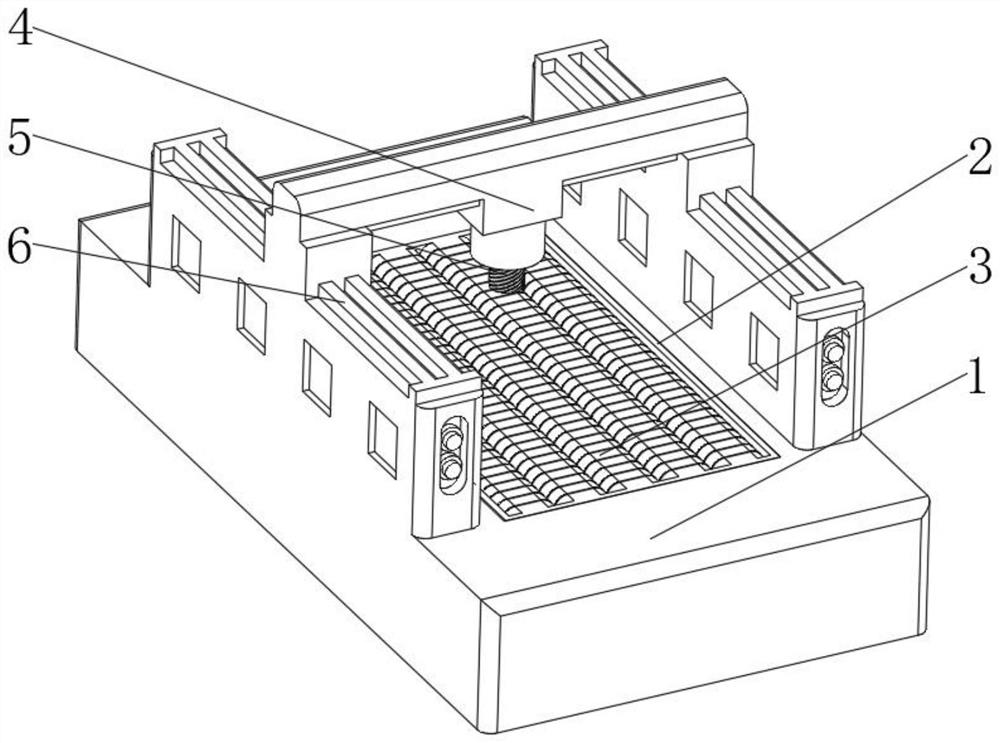
[0037] see Figure 1-2 , the present invention provides a technical solution: a gantry milling machine with enhanced workpiece positioning, specifically comprising:

[0038] Milling machine seat 1, this milling machine seat 1 has back-shaped seat plate, and the mosaic hole groove 2 that is offered at the middle position of the back-type seat plate top, and is installed in the positioning mechanism 3 of mosaic hole groove 2 bottoms;

[0039] Milling machine processor 4, this milling machine processor 4 has processing motor, and the milling machine tool 5 that is installed on the output end of processing motor, and is installed on the rail frame 6 on processing motor top, positioning mechanism 3 comprises:

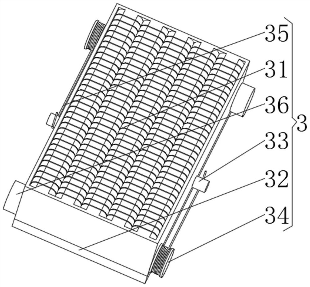
[0040] Fixing mechanism 31, this fixing mechanism 31 has a box-shaped main body, and a lifter 32 installed on the bottom of the box-shaped main body, and a reversing wheel 33 arranged at the middle position on both sides of the box-shaped main body;

[0041]Winding wheel 34...

Embodiment 2

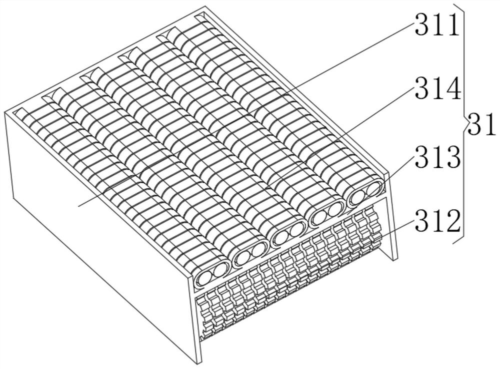
[0045] see Figure 1-3 , on the basis of implementing one, the present invention provides a technical solution: the fixing mechanism 31 includes:

[0046] Box 311, the box 311 has a square box, and an electromagnetic mechanism 312 installed at the bottom of the square box cavity, and an elastic partition 313 fixed on the square box cavity above the electromagnetic mechanism 312, and installed in the square box The cavity is located at the positioning mechanism 314 above the elastic partition 313 . Through the design of the elastic partition 313, the internal components are isolated from each other, avoiding the mutual contact of the components, and protecting them when the positioning mechanism 314 and the electromagnetic mechanism 312 move with each other. Perform offset absorption.

[0047] The bottom of the box body 311 is installed on the lifter 32 , the electromagnetic mechanism 312 is located directly above the lifter 32 , and the positioning mechanism 314 is located a...

Embodiment 3

[0050] see Figure 1-5 , on the basis of implementation one and embodiment two, the present invention provides a technical solution: The electromagnetic mechanism 312 includes:

[0051] Rotary column A1, the rotating column A1 has a cylinder, and the two ends of the cylinder pass through the box body 311 and extend to the outer surface of the box body 311;

[0052] Magnetic wheel A2, the magnetic wheel A2 has a central column, and a permanent magnet rod A3 fixed on the outer surface of the central column, and a contact gear A4 fixed on the outer end of the permanent magnet rod A3. Through the mutual cooperation of the traction wire 35 and the spring coil 36 in the first embodiment, the components of the rotating column A1 are driven, and the magnetic field transformation generated by the rotation of the magnetic wheel A2 and the permanent magnet rod A3 is used to realize the change of the magnetic force of the equipment , while providing the initial fixing force, the adsorpti...


PUM


Abstract

The invention discloses a planer type milling machine capable of strengthening workpiece positioning. The planer type milling machine specifically comprises a milling machine base which is provided with a concentric-square-shaped base plate and a positioning mechanism installed at the bottom of an inlaying hole groove; and the positioning mechanism comprises a fixing mechanism which is provided with a box-shaped body, reversing wheels arranged in the middles of the two sides of the box-shaped body, a winding wheel with a cylindrical wheel body, a pull wire installed on the surface of the cylindrical wheel body and a clockwork spring ring fixed to the position, opposite to the outer wall of the side, corresponding to the cylindrical wheel body, of the box type body. The invention relates to the technical field of robot conveying equipment. Components are connected through the pull wire, the pull wire is driven to move uninterruptedly, a power source is provided for the whole equipment, meanwhile, the pull wire has toughness, impact force generated when the pull wire is stretched is buffered to a certain degree, stress between the internal components is reduced, and abrasion protection on the components is achieved, so that the service life of the components is prolonged.

Description

technical field [0001] The invention relates to the technical field of gantry milling machines, in particular to a gantry milling machine with enhanced workpiece positioning. Background technique [0002] The lathe bed both sides of existing gantry milling machine forms portal frame by column and beam frame, and beam frame can do lifting motion along the guide rail on the column of both sides. There are 1 to 2 milling heads with vertical spindles on the beam frame, and the milling heads can move laterally along the guide rail of the beam frame. A ram is hung on one side of the column on both sides, and a milling head with a horizontal main shaft is installed in the ram. The ram drives the milling head to move up and down along the guide rail of the column. [0003] According to Chinese patent CN102275077B, the double column adopts a frame-type hollow structure, the saddle and the ram are arranged between the two supporting columns of the column, and the weight of the saddle...

Claims


Application Information

Patent Timeline
Patent Type & Authority Applications(China)
IPC IPC(8): B23C1/06B23Q1/01B23Q3/00
CPCB23C1/06B23Q1/012B23Q3/00
Inventor 和跃
Owner 和跃
Why Eureka
Try Eureka