
RSSI (Received Signal Strength Indication)-based filtering method and system

A numerical and integer technology, applied in the field of RSSI-based filtering method and its system, can solve the problems of difficult parameter adjustment and inability to reflect the rapid movement of the target position, so as to reduce pulse interference, overcome the instability of RSSI value, and achieve stable waveform. Effect

Active Publication Date: 2016-06-29
XIAMEN MEIYA PICO INFORMATION
View PDF4 Cites 4 Cited by
  • Summary
  • Abstract
  • Description
  • Claims
  • Application Information

AI Technical Summary

Problems solved by technology

However, the use of FIR filtering will cause the output RSSI value to be too flat, unable to reflect the rapid movement of the target position, and the traditional IIR is used in the IIR filter in this method, and the parameter adjustment is not easy

Method used


Image

  • RSSI (Received Signal Strength Indication)-based filtering method and system
  • RSSI (Received Signal Strength Indication)-based filtering method and system
  • RSSI (Received Signal Strength Indication)-based filtering method and system

Examples


Embodiment 1

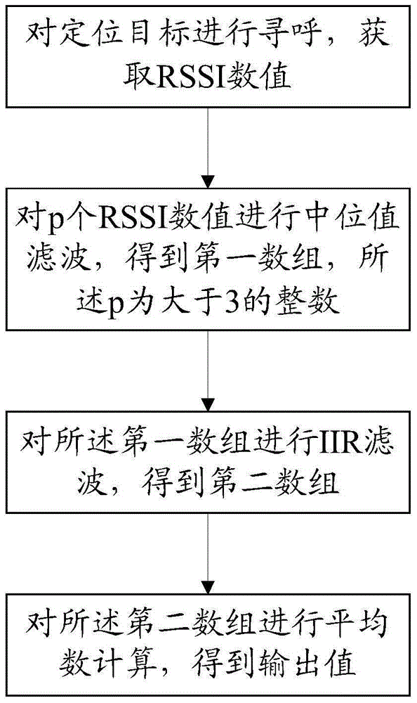
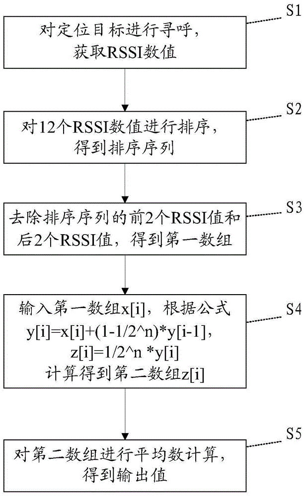
[0062] Please refer to Figure 1-2 , Embodiment 1 of the present invention is: a filtering method based on RSSI, which can be applied to wireless positioning technology, comprising the following steps:

[0063] S1: Paging the positioning target to make it report the RSSI value, so as to obtain the RSSI value.

[0064] S2: When the RSSI values ​​​​reach p, sort the p RSSI values ​​to obtain a sorting sequence; wherein p is an integer greater than 3, and the preferred value range is 12-20. In this embodiment, p is 12, that is, 12 The obtained RSSI values ​​are sorted, optionally, they can be sorted from large to small, or from small to large.

[0065] S3: Remove the first q RSSI values ​​and the last q RSSI values ​​of the sorting sequence to obtain the first array; wherein, q is an integer greater than 0, preferably in the range of 2-5, and in this embodiment, q is 2 , that is, after removing the first 2 RSSI values ​​and the last 2 RSSI values, the number of numbers in the f...

Embodiment 2

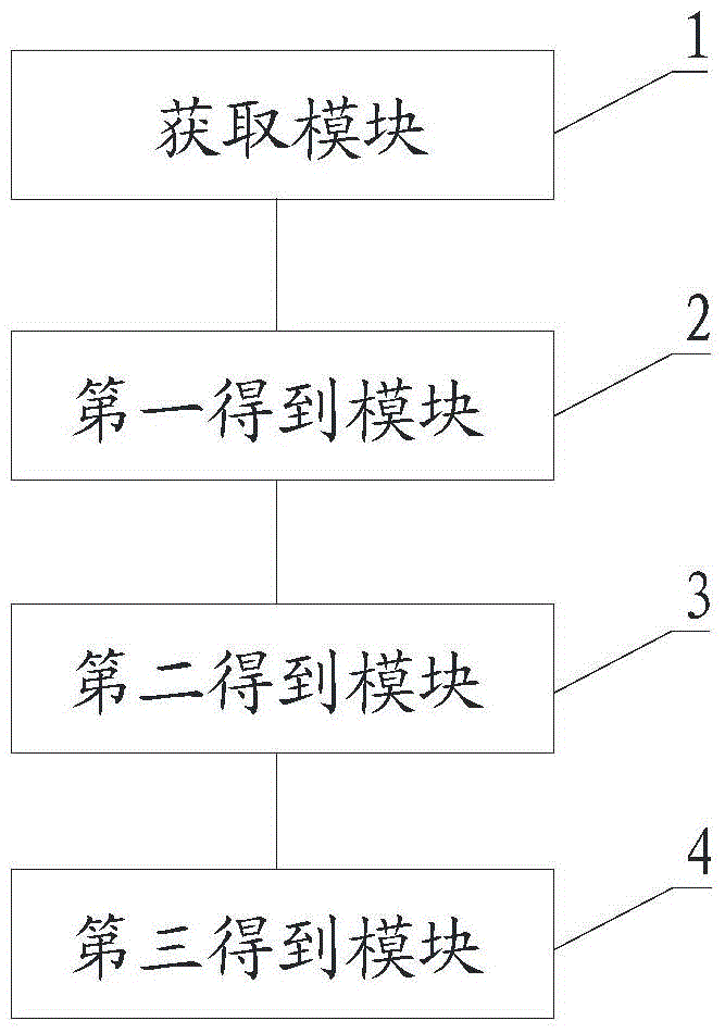
[0070] Please refer to Figure 3-4 , Embodiment 2 of the present invention is an RSSI-based filtering system corresponding to the above method, including

[0071] Obtaining module 1, used for paging the positioning target and obtaining the RSSI value;

[0072] The first obtaining module 2 is used to perform median value filtering on p RSSI values ​​to obtain a first array, and the p is an integer greater than 3;

[0073] The second obtaining module 3 is used to perform IIR filtering on the first array to obtain a second array;

[0074] The third obtaining module 4 is configured to perform average calculation on the second array to obtain an output value.

[0075] The first obtaining module 2 includes

[0076] An acquisition unit 21, configured to acquire p RSSI values;

[0077] A sorting unit 22, configured to sort the p RSSI values ​​to obtain a sorted sequence;

[0078] The removing unit 23 is configured to remove the first q RSSI values ​​and the last q RSSI values ​​i...


PUM


Abstract

The invention discloses an RSSI (Received Signal Strength Indication)-based filtering method and system. The method comprises the following steps: paging a positioning target to obtain RSSI numerical values; performing median value filtering on p RSSI numerical values to obtain a first array, wherein p is an integer being greater than 3; performing IIR (Infinite Impulse Response) filtering on the first array to obtain a second array; and calculating a mean value of the second array to obtain an output value. The median value filtering is performed on the RSSI numerical values, so that the influence on pulse interference is lowered, and the defects of unstable input RSSI values and great fluctuation can be overcome. Through the IIR filtering, the contradiction of excessive output fluctuation due to an overlarge input proportion is overcome. The IIR filtering is performed on the RSSI numerical values being subjected to the median value filtering, so that an output waveform is smoothened effectively, and becomes more stable.

Description

technical field [0001] The present invention relates to the technical field of RSSI positioning, in particular to an RSSI-based filtering method and system thereof. Background technique [0002] With the rapid development of computer technology, Internet technology and wireless technology, the demand for wireless positioning services in military and civilian fields is increasing day by day. In the wireless positioning system, it mainly includes positioning technology based on RSSI (Received Signal Strength Indication), positioning technology based on signal time of arrival (Time-of-Arrival: TOA) and signal angle-of-arrival (Angle-of-Arrival: AOA). AOA technology requires a special antenna array, which is expensive and difficult to implement. TOA technology requires strict time synchronization, otherwise it will cause clock deviation and affect positioning accuracy. However, RSSI information is easier to obtain and does not require time synchronization. Therefore, in practi...

Claims


Application Information

Patent Timeline
Patent Type & Authority Applications(China)
IPC IPC(8): H03H17/00G01S5/02
CPCG01S5/0205G01S5/0215H03H17/00H03H2017/009
Inventor 潘锟梁瑞彬张永光汤伟宾吴鸿伟滕达
Owner XIAMEN MEIYA PICO INFORMATION
Learn More