
Magnetic probe cable anchor with metal marker bands

A metal strip, magnetic technology, applied in the direction of magnets of measuring devices, parts of connecting devices, parts of electrical measuring instruments, etc.

Inactive Publication Date: 2016-07-06
TEKTRONIX INC
View PDF8 Cites 0 Cited by
  • Summary
  • Abstract
  • Description
  • Claims
  • Application Information

AI Technical Summary

Problems solved by technology

[0003] When the probe tip is connected to the DUT, any motion or force from the circuit board assembly or the probe assembly (including cables) will be transferred to the thin wire connection between the DUT and the probe tip, undesirably and disadvantageously lead to disconnection of the electrical path

Method used


Image

  • Magnetic probe cable anchor with metal marker bands
  • Magnetic probe cable anchor with metal marker bands
  • Magnetic probe cable anchor with metal marker bands

Examples


Embodiment Construction

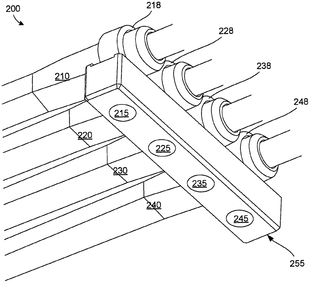
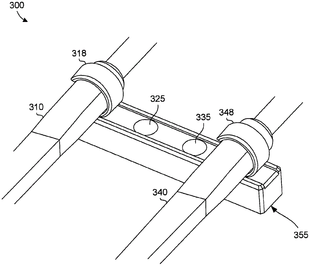
[0009] Embodiments of the disclosed technology generally relate to various systems and methods for providing protection, for example, from impact or other inadvertent movement that would cause test probes (including test probes) positioned at or near one or more connection points probe tip) to the interruption or even complete disconnection of the electrical connection to the device under test (DUT).

[0010] Certain embodiments of the disclosed technology include flex circuits and flex connectors that are small, light, flexible, and provide a flat surface for easy attachment (e.g., VHB tape or glue) to a printed circuit board ( PCB).

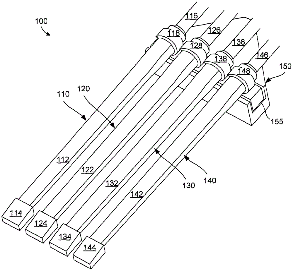
[0011] figure 1 A first example 100 of test probes 110 , 120 , 130 , and 140 is shown securely coupled with a magnetic anchor base assembly 150 in accordance with certain embodiments of the disclosed technology. Each test probe 110, 120, 130, and 140 includes a flexible body 112, 122, 132, and 142, respectively, and includes a cable 116, 126,...


PUM


Abstract

A magnetic anchor base assembly can include a magnetic coupling component and magnetic sub-components integrated therewith. Each magnetic sub-component can be configured to magnetically couple with a metal band that is configured to couple with a test probe.

Description

technical field [0001] The present disclosure generally relates to test probes and other devices for testing circuit boards and devices thereon. Background technique [0002] Today's probing applications require test probes to be attached to very small devices on the board for testing. These connections from the probe tip to the device under test (DUT) are usually made with very thin wire (eg, 0.004-0.008"). A typical probe assembly usually consists of a compensation box mounted to the oscilloscope, a certain length (eg, 36-47") coaxial cable, and test probes with probe tips. [0003] When the probe tip is connected to the DUT, any motion or force from the circuit board assembly or the probe assembly (including cables) will be transferred to the thin wire connection between the DUT and the probe tip, undesirably and disadvantageously resulting in disconnection of the electrical path. Previously attempted solutions included taping or gluing the probe tips to the circuit bo...

Claims


Application Information

Patent Timeline
IPC IPC(8): G01R13/00G01R1/073
CPCG01R1/07307G01R13/00G01R1/04G01R1/073G01R1/16H01R13/6205H01R2201/20G01R31/2889G01R1/0416
Inventor J·H·麦克格拉思
Owner TEKTRONIX INC
Learn More