
Multi-focal lens ultra-high resolution linkage imaging device

An ultra-high-resolution, imaging device technology, applied in image communication, television, closed-circuit television systems, etc., can solve the problems of monitoring omission, difficult to take into account the clear imaging of long-range targets, and full coverage monitoring of the entire scene.

Active Publication Date: 2018-10-19
HUNAN VISION SPLEND PHOTOELECTRIC TECH
View PDF5 Cites 0 Cited by
  • Summary
  • Abstract
  • Description
  • Claims
  • Application Information

AI Technical Summary

Problems solved by technology

[0003] The purpose of the present invention is to provide a multi-focus lens ultra-high-resolution linkage imaging device, which solves the problem that it is difficult to take into account the clear imaging of distant objects and the overall The limitation of full-coverage monitoring of the scene; and the technical problem of monitoring omission caused by the camera pan-tilt device switching between close-range imaging and long-range imaging

Method used


Image

  • Multi-focal lens ultra-high resolution linkage imaging device
  • Multi-focal lens ultra-high resolution linkage imaging device
  • Multi-focal lens ultra-high resolution linkage imaging device

Examples


Embodiment Construction

[0043] The accompanying drawings constituting a part of this application are used to provide further understanding of the present invention, and the schematic embodiments and descriptions of the present invention are used to explain the present invention, and do not constitute an improper limitation of the present invention.

[0044] In order to overcome the deficiencies in the application of video surveillance in a large area in the existing surveillance solutions, the present invention provides a multi-focus lens ultra-high resolution linkage imaging device. It only needs to install a set of equipment in the monitoring area, which can replace all the monitoring equipment required in the existing monitoring scheme, and it is easy to operate and use. The device includes a video capture module, a storage module 300 and a video management module 400 .

[0045] see figure 1 The video acquisition module includes at least one overview acquisition unit 110 and at least ten detail a...


PUM


Abstract

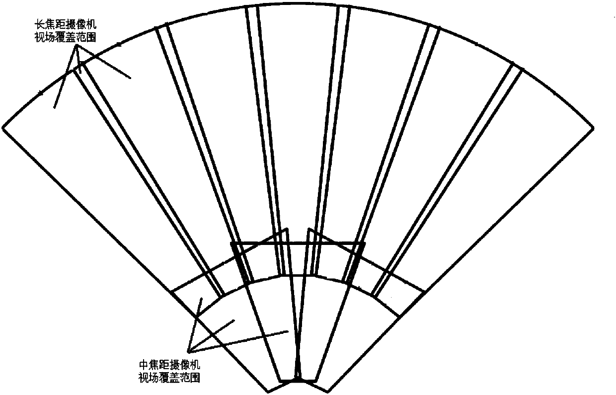
The present invention provides a multi-focus lens ultra-high-resolution linkage imaging device. The device monitors a large area at the same time by using a multi-focus lens, and the super-resolution image obtained by collecting the lateral field of view angle is greater than 90°, so that the The device can achieve full coverage without blind spots in large-scale scene monitoring, and within 130m from the device, the pixel density of the collected images is greater than 125 pixels / m, making the pixels of the entire monitoring image reach more than 100 million.

Description

technical field [0001] The invention relates to the field of image imaging technology, in particular to a multi-focus lens ultra-high resolution linkage imaging device. Background technique [0002] At present, in the video monitoring schemes of large-scale areas such as government squares, large parking lots, airport waiting halls, and station waiting halls, the existing monitoring schemes mainly use multiple bolts and high-speed balls to cooperate. The existing long-focus lens bolts have a limited field of view; and the bolts equipped with short-focus lenses can only obtain target images with insufficient pixels for distant targets; There will be blind spots when using the entire scene and local specific enlarged images. For the user, it is very inconvenient to switch between the images of multiple cameras when adopting this monitoring solution, which reduces the monitoring efficiency and increases the difficulty of monitoring. Therefore, the existing monitoring scheme h...

Claims


Application Information

Patent Timeline
Patent Type & Authority Patents(China)
IPC IPC(8): H04N7/18H04N5/225H04N5/232
CPCH04N7/18H04N23/00H04N23/698H04N23/69
Inventor 刘述杰张弘强
Owner HUNAN VISION SPLEND PHOTOELECTRIC TECH
Learn More