Wear-resisting pin shaft

A technology of wear-resistant pins and pin shafts, applied in the direction of chain elements, belts/chains/gears, mechanical equipment, etc., can solve the problems of easy initiation of cracks on the surface, fatigue fractures, etc., to reduce fatigue fractures, increase service life, improve durability abrasive effect

Inactive Publication Date: 2016-07-13
SUZHOU UNIVERSAL GRP TECH CO LTD
View PDF6 Cites 0 Cited by
  • Summary
  • Abstract
  • Description
  • Claims
  • Application Information

AI Technical Summary

Problems solved by technology

However, if the conventional induction hardening method is adopted, since the induction hardening is much higher than the base of the pin shaft, after the pin shaft is bent under load, the surface is prone to cracks, and fatigue fractures often occur during use.

Method used


Image

  • Wear-resisting pin shaft
  • Wear-resisting pin shaft

Examples


Embodiment Construction

[0010] The preferred embodiments of the present invention will be described in detail below in conjunction with the accompanying drawings, so that the advantages and features of the present invention can be more easily understood by those skilled in the art, so as to define the protection scope of the present invention more clearly.

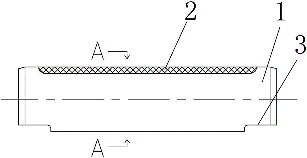
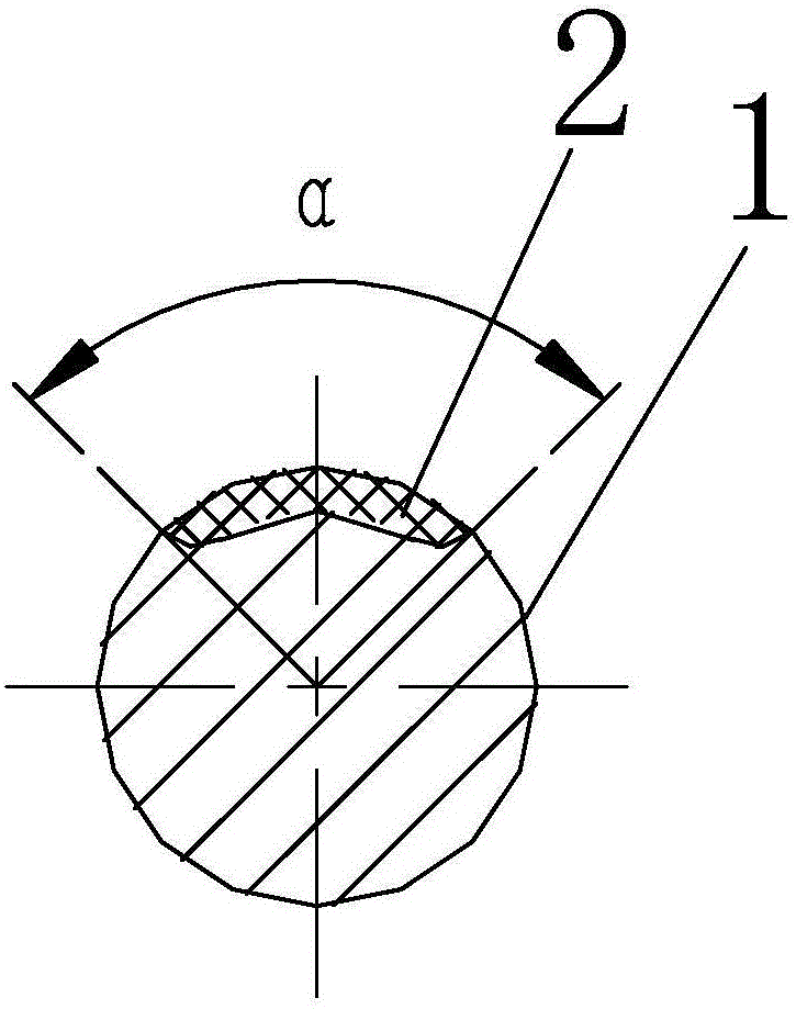
[0011] see figure 1 with figure 2 , the embodiment of the present invention includes:

[0012] In order to solve the above technical problems, a technical solution adopted by the present invention is a wear-resistant pin shaft, comprising: a pin shaft body 1; an induction hardening layer 2 is provided on the outer surface of the upper part of the pin shaft body 1; Both ends of the lower part of 1 are provided with a notch 3, and the notch 3 is flat, which is beneficial to confirm the direction during assembly; the angle of the induction hardened layer 2 is 45°-75°.

[0013] The beneficial effect of the present invention is: a kind of wear-resi...


PUM


Abstract

The invention discloses a wear-resisting pin shaft which comprises a pin shaft body.The outer surface of the upper portion of the pin shaft body is provided with an induction quenching layer, and the two ends of the lower portion of the pin shaft body are each provided with a gap.In this way, the wear resistance of the pin shaft is improved; meanwhile, after the pin shaft bears loads to be bent, the surface of the pin shaft body is not prone to cracks, fatigue fractures occurring in the using process are reduced, and the service life of the wear-resisting pin shaft is prolonged.

Description

technical field [0001] The invention relates to an improvement of a pin shaft, in particular to improving the wear resistance of the pin shaft; at the same time, after the pin shaft is bent under load, the surface of the pin shaft body is not prone to cracks, reducing fatigue fractures during use; increasing the use of Long life wear-resistant pin. Background technique [0002] The pin shaft is one of the parts on the chain. The pin shaft of an ordinary chain is usually quenched and tempered as a whole. Chains used in special environments, in order to improve their wear resistance, also have surface induction hardening treatment. However, if the conventional induction hardening method is adopted, since the induction hardening is much higher than the base of the pin shaft, after the pin shaft is bent under load, cracks are easy to occur on the surface, and fatigue fractures often occur during use. Contents of the invention [0003] The technical problem mainly solved by t...

Claims


Application Information

Patent Timeline
Patent Type & Authority Applications(China)
IPC IPC(8): F16G15/00
CPCF16G15/00
Inventor 黄伟达
Owner SUZHOU UNIVERSAL GRP TECH CO LTD
Why Eureka
Try Eureka