Ring knock-off protection structure for conical ring variable speed unit

A technology of continuously variable transmission and protective structure, which is applied to transmission parts, friction transmission devices, belts/chains/gears, etc., which can solve problems such as parts damage, and achieve the effect of avoiding shaft shoulder impact and component damage

Active Publication Date: 2016-07-13
浙江富康创业投资有限公司
View PDF5 Cites 0 Cited by
  • Summary
  • Abstract
  • Description
  • Claims
  • Application Information

AI Technical Summary

Problems solved by technology

[0008] In order to overcome the problem of parts damage in the limit crash stop of the existing KRG transmission ring, t

Method used


Image

  • Ring knock-off protection structure for conical ring variable speed unit
  • Ring knock-off protection structure for conical ring variable speed unit
  • Ring knock-off protection structure for conical ring variable speed unit

Examples


Example Embodiment

[0041] Example 1

[0042] Reference attached Figure 5a , 5c , 7, 8a, 8b, 8c, 11:

[0043] The ring crash protection structure for the cone-ring type continuously variable transmission includes a first transmission cone 2, a transmission ring 1. The surface of the first transmission cone 2 is in contact with a surface of the transmission ring 1, and the first transmission cone 2 The small end is provided with a shoulder 21 opposite to the tapered surface 22, and the shoulder 21 has the shape of a revolving body; the transmission ring 1, the shoulder 21, and the tapered surface 22 have the following geometric matching relationship: when the transmission ring 1 When contacting the shaft shoulder 21, there is a first contact point 211 between the transmission ring 1 and the shaft shoulder 21, and there is a second contact point 221 between the transmission ring 1 and the cone surface. The distance between the first contact point 211 and the cone axis P Is the first contact radius r 1...

Example Embodiment

[0052] Example 2

[0053] Reference attached Figure 6a , 6c , 9, 10a, 10b, 10c, 12:

[0054] The difference between this embodiment and embodiment 1 is: the third transmission component is the second transmission cone 20, the second transmission cone 20 is the input cone, the transmission ring 1 is sleeved on the second transmission cone 20, A transmission cone 30 is an output cone; the cone generatrix of the first transmission cone 30 is parallel to the cone generatrix of the second transmission cone 20. The taper of the first transmission cone 30 and the second transmission cone 20 can be different, such as Figure 6a Shown; when the taper of the two is the same, such as Figure 6c As shown, the cone axes P of the first transmission cone 30 and the second transmission cone 20 are parallel to each other, and the large end and the small end are arranged oppositely.

[0055] On the shaft section made through the cone axis P, the tangent 3111 of the generatrix 312 of the shoulder 31 ...

Example Embodiment

[0062] Example 3

[0063] Reference Figure 5b , 7 , 8a, 8b, 8c, 11, the difference between this embodiment and Embodiment 1 is: the third transmission component is a cylinder, and the rest are the same.

[0064] In addition, the third transmission component may also be a rotating body other than a cylinder and a cone.

[0065] The working process is similar to that of Example 1.


PUM


Abstract

The invention discloses a ring knock-off protection structure for a conical ring variable speed unit. The structure comprises a first transmission cone and a transmission ring, wherein the surface of the first transmission cone is in contact with one surface of the transmission ring; a shaft shoulder opposite to the cone surface is arranged at the small end of the first transmission cone; the shaft shoulder has a rotation body shape; the transmission ring, the shaft shoulder and the cone surface have the following geometrical matching relation; when the transmission ring is in contact with the shaft shoulder, a first contact point is formed between the transmission ring and the shaft shoulder; meanwhile, a second contact point is formed between the transmission ring and the cone surface; the distance from the first contact point to a cone axis is a first contact radius; the distance from the second contact point to the cone axis is a second contact radius; the first contact radius is smaller than the second contact radius. When the transmission ring is operated in a shaft shoulder extreme position at the small end of an input cone or an output cone, the transmission ring can prevent from impacting the shaft shoulder, and component damage is avoided.

Description

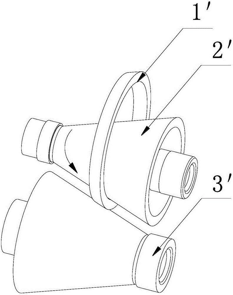
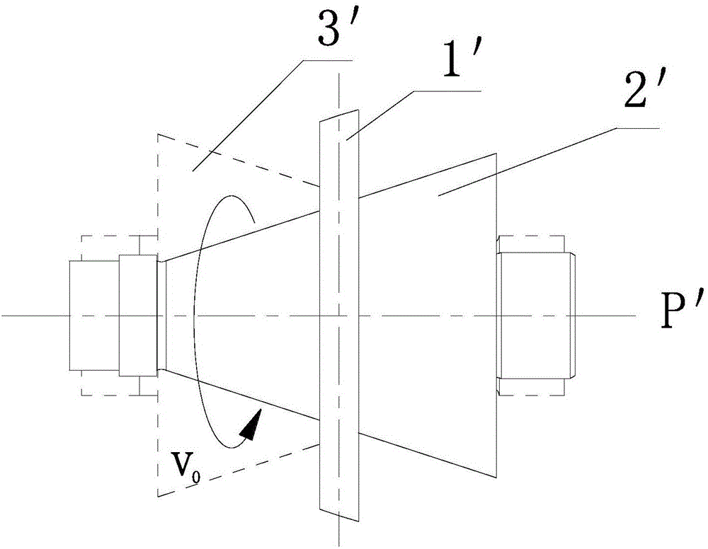
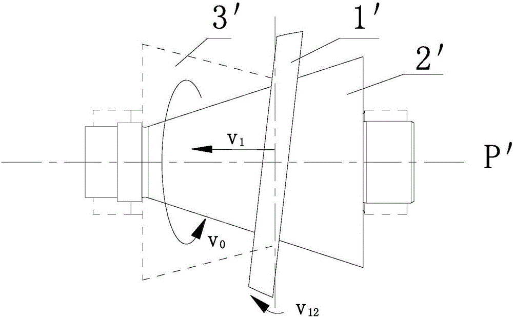
technical field [0001] The invention relates to a ring crash protection structure for a cone ring type continuously variable transmission. Background technique [0002] The cone-ring continuously variable transmission (hereinafter referred to as KRG) is a continuously variable transmission that uses the input cone and the output cone to clamp the transmission ring and is driven by friction. KRG's design philosophy is to avoid hydraulic pumps in any way and use only simple and durable mechanical parts controlled by electric motors. Compared with conventional continuously variable transmission (CVT), this design concept of KRG gives it a huge advantage in terms of manufacturing cost and efficiency. [0003] Such as figure 1 As shown, in the KRG transmission, the input cone 2' and the output cone 3' clamp the transmission ring 1', and the inner and outer surfaces of the transmission ring 1' generate friction with the input cone 2' and output cone 3' respectively, and the powe...

Claims


Application Information

Patent Timeline
IPC IPC(8): F16H15/42F16H57/00
CPCF16H15/42F16H57/00
Inventor 刘波董恩东
Owner 浙江富康创业投资有限公司
Why Eureka
Try Eureka