
Engine speed-limiting system and vehicle

An engine and limit column technology, applied in the direction of engine control, machine/engine, mechanical equipment, etc., can solve problems such as accelerator pedal, accelerator cable and throttle damage, and achieve the effect of preventing damage to parts

Active Publication Date: 2018-07-03
BEIQI FOTON MOTOR CO LTD
View PDF5 Cites 0 Cited by
  • Summary
  • Abstract
  • Description
  • Claims
  • Application Information

AI Technical Summary

Problems solved by technology

In related technologies, the accelerator is mostly controlled by a mechanical pull-wire mechanism. One end of the steel wire is connected to the accelerator pedal, and the other end is connected to the throttle valve. The stepping depth will also be limited. If the driver steps on the accelerator hard when the power take-off switch is turned on, it will cause damage to parts such as the accelerator pedal, accelerator cable or throttle, and there is room for improvement.

Method used


Image

  • Engine speed-limiting system and vehicle
  • Engine speed-limiting system and vehicle
  • Engine speed-limiting system and vehicle

Examples


Embodiment Construction

[0030] Embodiments of the present invention are described in detail below, examples of which are shown in the drawings, wherein the same or similar reference numerals designate the same or similar elements or elements having the same or similar functions throughout. The embodiments described below by referring to the figures are exemplary and are intended to explain the present invention and should not be construed as limiting the present invention.

[0031] In the description of this specification, descriptions referring to the terms "one embodiment", "some embodiments", "example", "specific examples", or "some examples" mean that specific features described in connection with the embodiment or example , structure, material or characteristic is included in at least one embodiment or example of the present invention. In this specification, the schematic representations of the above terms are not necessarily directed to the same embodiment or example. Furthermore, the describe...


PUM


Abstract

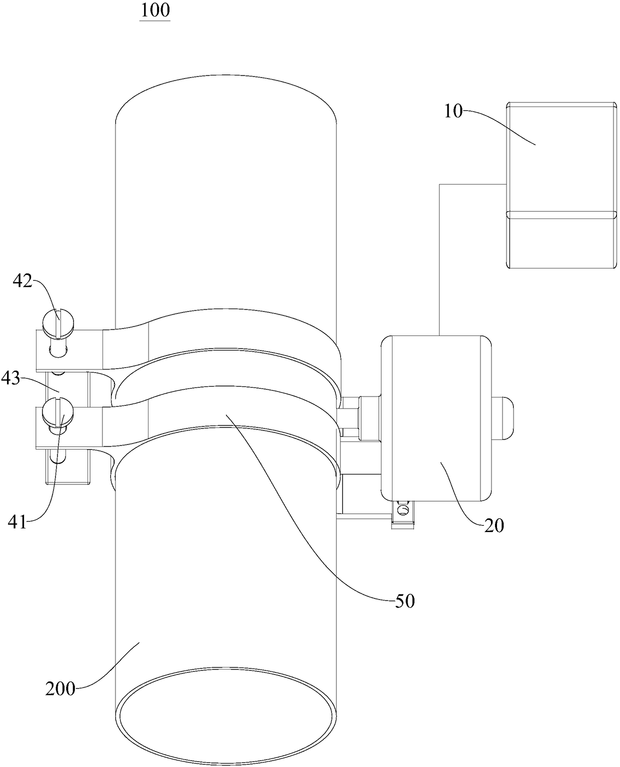
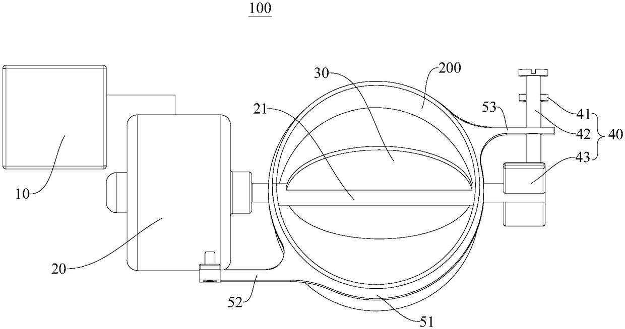
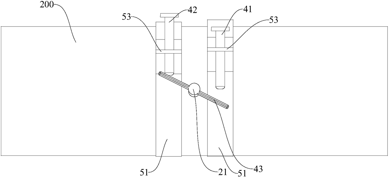
The invention discloses an engine speed-limiting system and a vehicle. The engine speed-limiting system comprises a shielding part, a driving unit, a control unit and a limiting part. The shielding part is rotatably arranged in an air inlet pipe of the engine so as to selectively adjust the air inlet section area; the driving unit is connected with the shielding part; the control unit is connectedwith the driving unit; and the limiting part is mounted on the air inlet pipe so as to limit the rotating angle of the shielding part. According to the engine speed-limiting system, the air inlet amount of an engine is limited in an electric control mode, and the limiting part can effectively control the air inlet amount so that the output rotating speed of the engine can be controlled; and as for the vehicle provided with a power take-off, the situation that parts are damaged due to hard stepping of an accelerator pedal can be prevented.

Description

technical field [0001] The invention belongs to the technical field of vehicle manufacturing, and in particular relates to an engine speed limiting system and a vehicle with the engine speed limiting system. Background technique [0002] Power take-offs are widely used in various vehicles. Quite a few power take-offs directly draw power from the engine. In order to protect the power take-off, it is necessary to limit the engine speed to prevent the input speed of the power take-off from being too high. In related technologies, the accelerator is mostly controlled by a mechanical pull-wire mechanism. One end of the steel wire is connected to the accelerator pedal, and the other end is connected to the throttle valve. The stepping depth will also be limited. If the driver steps on the accelerator hard when the power take-off switch is turned on, it will cause damage to parts such as the accelerator pedal, accelerator cable or throttle, and there is room for improvement. Cont...

Claims


Application Information

Patent Timeline
IPC IPC(8): F02D9/10
CPCF02D9/10F02D9/1065
Inventor 刘金宝郑豹岳言亮
Owner BEIQI FOTON MOTOR CO LTD
Learn More