Rotary sliding device

A pulley frame and pulley assembly technology, applied in the field of rotatable sliding devices, can solve the problems of inability to rotate and turn, limited span, limited use, etc., and achieve the effect of ensuring stability, wide application range, and ensuring stability

Inactive Publication Date: 2016-07-20
XIAN JUNANG OUTDOOR SPORT CLUB
View PDF7 Cites 0 Cited by
  • Summary
  • Abstract
  • Description
  • Claims
  • Application Information

AI Technical Summary

Problems solved by technology

[0002] The forms of the current ziplines are all straight lines, generally steel wire ropes, and the combination of pulleys matched with the steel wire ropes is used to realize long-distance zipline activities. Since the steel wire rope itself is pulled by two points, the pulley must Sliding on the wire rope, other supports cannot be used in the middle of the wire rope. The span of this combination is very limited. If the distance is long, the load-bearing capacity can only be increased by thickening the wire rope. Due to the ductility of the wire rope, this soft The safety protection of the connection is not good, and it will cause floating; in addition, the steel wire rope can only be pulled by two points, and the form of the zipline can only be a straight line, and it cannot rotate or turn, and there are many restrictions on use.

Method used


Image

  • Rotary sliding device
  • Rotary sliding device
  • Rotary sliding device

Examples


Embodiment Construction

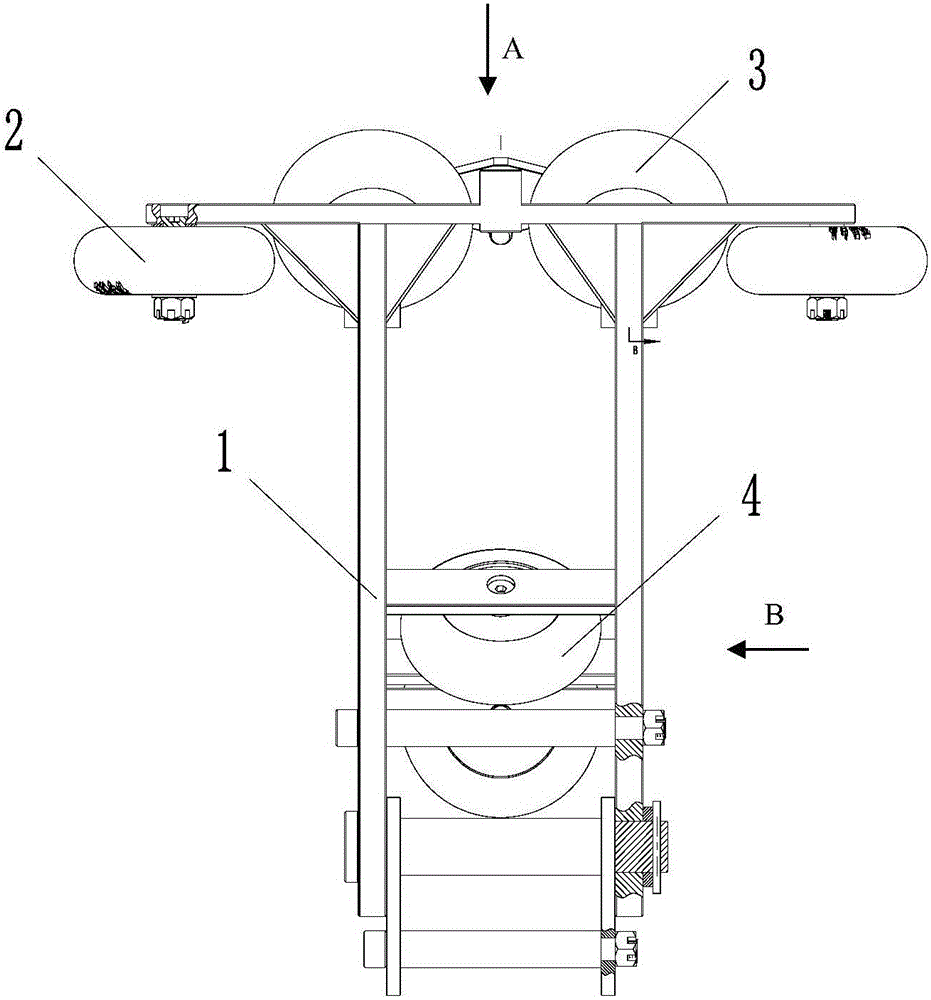
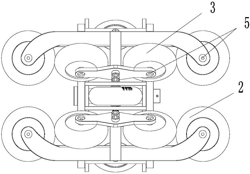
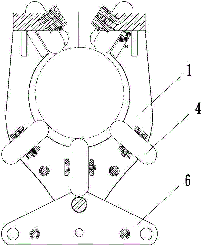
[0022] see figure 1 , figure 2 as well as image 3 , the present invention is a rotatable sliding device, including a track and a pulley assembly sliding on the track, the pulley assembly includes a pulley frame 1, a guide wheel set 2 and a bearing wheel set 3; the pulley frame 1 is sleeved on the track, and the track The cross section is circular, and the track is in the form of N sections of small tracks connected sequentially; the shape of the inner ring of the pulley frame 1 and the shape of the track are adapted to be circular, and the upper part of the pulley frame 1 is provided with a guide wheel set 2 and a load-bearing wheel set 3; the pulley frame The lower part of 1 is provided with a supporting limit wheel group 4; the load-bearing wheel set 3 includes 4 symmetrically arranged load-bearing wheels, and the 4 load-bearing wheels are symmetrically arranged on the two horizontal frames on the upper part of the pulley frame; the upper surface of the load-bearing wheel...


PUM


Abstract

The invention relates to a rotary sliding device. The rotary sliding device comprises a rail and a sliding wheel assembly, wherein the sliding wheel assembly slides on the rail. The sliding rail assembly comprises a sliding wheel frame, a guiding wheel set and a bearing wheel set. The sliding wheel frame is connected to the rail in a sleeving mode. The shape of the inner circle of the sliding wheel frame is matched with the shape of the rail. The guiding wheel set and the bearing wheel set are arranged on the upper portion of the sliding wheel frame. A supporting and limiting wheel set is arranged on the lower portion of the sliding wheel frame. The bearing wheel set comprises two or more bearing wheels which are symmetrically arranged, and the bearing wheels are arranged obliquely relative to the upper surface of the rail. Guiding wheels are arranged at the two ends of the upper portion of the sliding wheel frame and are parallel to the rail. According to the rotary sliding device, the rail is formed by connecting round pipes one by one in an abutting mode, and the rail is bendable so that steering and rotating during sliding can be achieved; the application range is wide, specifically, the rotary sliding device can be suitable for various indoor and outdoor environments, and rising, falling and encircling of the rail can be achieved when the rotary sliding device is used indoors; and the rotary sliding device can be used between mountains outdoors, and the stability of the long-span rail can be guaranteed.

Description

technical field [0001] The invention relates to a sliding cable device, in particular to a rotatable sliding device. Background technique [0002] The forms of the current ziplines are all straight lines, generally steel wire ropes, and the combination of pulleys matched with the steel wire ropes is used to realize long-distance zipline activities. Since the steel wire rope itself is pulled by two points, the pulley must Sliding on the wire rope, other supports cannot be used in the middle of the wire rope. The span of this combination is very limited. If the distance is long, the load-bearing capacity can only be increased by thickening the wire rope. Due to the ductility of the wire rope, this soft The safety protection of the connection is not good, and it will cause floating; in addition, the wire rope can only be pulled by two points, and the form of the zipline can only be a straight line, and it cannot rotate or turn, and there are many restrictions on use. Contents...

Claims


Application Information

Patent Timeline
Patent Type & Authority Applications(China)
IPC IPC(8): B61B7/04B61B12/02B61B12/12
CPCB61B7/04B61B12/02B61B12/122
Inventor 李强
Owner XIAN JUNANG OUTDOOR SPORT CLUB
Why Eureka
Try Eureka