Supercharge Your Innovation With Domain-Expert AI Agents!

Brake force monitor for elevator brakes

A technology of brakes and monitors, applied in the field of elevators, can solve the problems of readings deviating from the original calibration state, expensive, sensor drift, etc.

Active Publication Date: 2018-02-13
INVENTIO AG
View PDF4 Cites 0 Cited by
  • Summary
  • Abstract
  • Description
  • Claims
  • Application Information

AI Technical Summary

Problems solved by technology

All force sensors, no matter what they're made of, how expensive they are, or how accurate they are, are prone to sensor drift over time
Sensor drift is the gradual degradation of the sensor which can cause readings to deviate from their original calibrated state

Method used


Image

  • Brake force monitor for elevator brakes
  • Brake force monitor for elevator brakes
  • Brake force monitor for elevator brakes

Examples


Embodiment Construction

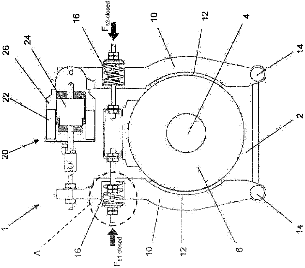
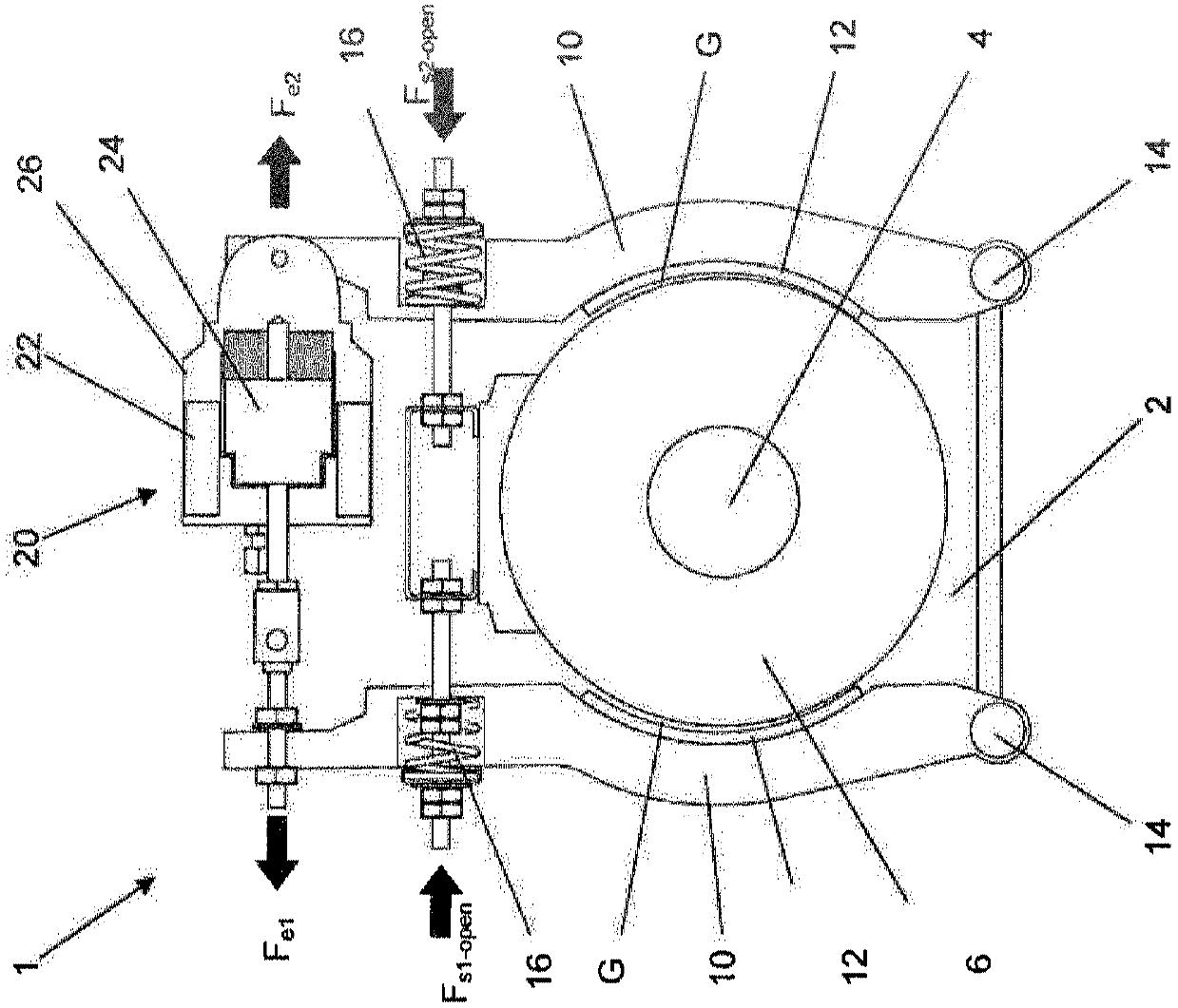
[0035] figure 1 and figure 2 is a schematic plan view of the same elevator brake 1 . figure 1 depicts brake 1 in its closed position, while figure 2 The brake 1 is shown in its open position. The brake 1 comprises a brake drum 6 mounted directly to a shaft 4 connected directly to the motor, or alternatively indirectly via gears. Two brake arms 10 are arranged at opposite sides of the drum 6 and are mounted at their lower ends to pivots 14 connected to the housing 2 of the motor or gear. Each arm 10 is fitted with a brake pad 12 and is biased towards the drum 6 by a pre-tensioned compression spring 16 . The force exerted by the spring 16 on the brake arm 10 is represented by the arrow F s1 and F s2 show. The electromagnetic actuator 20 is disposed between and interconnects the upper ends of the brake arms 10 . The actuator 20 includes a housing 26 containing a series of solenoid coils 22 and a movable solenoid plunger 24 extending from the housing 26 .

[0036] in such...


PUM


Abstract

A method and apparatus for monitoring an elevator drive brake wherein the method includes the steps of detecting a spring force (Fs-closed) when the brake is closed, detecting a spring force (Fs-open) when the brake is open, determining the difference between the two detected spring forces (ΔFs), and comparing the difference between the two detected spring forces with at least one preset permissible force differential (ΔFsmin; ΔFsmax) to determine whether the brake is defective. The apparatus includes a force sensor for each brake spring to be monitored, and an electronic monitor that stores at least one preset permissible force differential (ΔFsmin; ΔFsmax) and, during operation, compares the at least one preset permissible force differential with an actual force difference (ΔFs) between an open spring force (Fs-open) and a closed spring force (Fs-closed) as detected by the force sensor.

Description

technical field [0001] The present disclosure relates to elevators, and more particularly, to methods and apparatus for monitoring spring forces within braking systems installed in conjunction with elevator motors. Although such equipment may be provided pre-assembled with braking system and motor as a drive for newly planned installations, it is contemplated that such equipment is particularly advantageous when supplied as a kit for modernizing existing installations . Background technique [0002] A brake is usually provided to stop the rotation of the motor in the traction elevator. The brakes include brake drums that are either mounted directly to the output shaft of the motor, or alternatively are indirectly connected via gears to the output shaft of the motor. At least one pivoting brake arm with a braking lining is biased towards the drum by a compression spring such that when the brake lining is closed frictionally engages a braking surface on the drum to stop the ...

Claims


Application Information

Patent Timeline
Patent Type & Authority Patents(China)
IPC IPC(8): B66D5/30B66D5/00B66D5/08
CPCB66B5/0031B66B1/34B66D5/08B66D5/30
Inventor 比亚内·林德伯格冈特拉姆.贝格勒约瑟夫·维特希
Owner INVENTIO AG
Features
  • R&D
  • Intellectual Property
  • Life Sciences
  • Materials
  • Tech Scout
  • Unparalleled Data Quality
  • Higher Quality Content
  • 60% Fewer Hallucinations
Learn More