
A calibration method for the probe tube of the inclinometer of a mining rotary drilling rig

A calibration method and technology of rotary drilling rigs, applied in the field of data fusion, can solve the problems of unfavorable small and micro enterprise production, high prices of three-axis Helmholtz coils and three-axis non-magnetic turntables, and low calibration accuracy

Active Publication Date: 2018-09-11
TAIYUAN UNIV OF TECH
View PDF2 Cites 0 Cited by
  • Summary
  • Abstract
  • Description
  • Claims
  • Application Information

AI Technical Summary

Problems solved by technology

For the calibration of the probe tube of the mining rotary drilling rig, the publication number is CN103089242A, which discloses "an active magnetic field calibration method", which uses a three-axis Helmholtz coil and a three-axis non-magnetic turntable for calibration. The axial Helmholtz coil and the three-axis non-magnetic turntable are expensive, which is not conducive to the production of small and micro enterprises; the second is that the calibration accuracy depends on the manufacturing process accuracy of the two instruments and the installation accuracy of the calibrated measurement unit during calibration. Error accumulation, low calibration accuracy
The publication number is CN104234696A, which discloses "an error model curve by constructing an attitude angle" and tabulates it, and then solves the calibration method of the attitude angle by means of a look-up table. Although this method also calibrates the measurement unit by a mathematical method, the The constructed list requires a large storage space, and this method does not solve the error problem from the level of the fundamental sensor error itself, and needs to further study the calibration of the three-axis combined sensor installed in the probe tube

Method used


Image

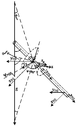
  • A calibration method for the probe tube of the inclinometer of a mining rotary drilling rig
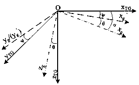
  • A calibration method for the probe tube of the inclinometer of a mining rotary drilling rig
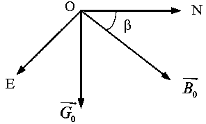
  • A calibration method for the probe tube of the inclinometer of a mining rotary drilling rig

Examples


Embodiment 1

[0026] On the basis of the above-mentioned specific implementation, further implement the calibration method of the probe tube of a kind of mining rotary drilling rig inclinometer, the calibration method is to first provide the error model of the three-axis sensor, and then give the error model according to the error model Implementation steps of the calibration method.

[0027] 1) Three-axis gravity acceleration sensor

[0028] Because there is no cross-axis interference in the three-axis gravity acceleration sensor, its error matrix is ​​an upper triangular matrix.

[0029]

[0030] where g TG is the three-axis component of the gravity vector in the probe (vehicle) coordinate system, g is the measured value of the three-axis gravity acceleration sensor in the earth's gravity environment, K g is the error matrix of the gravity acceleration sensor, b g is the zero drift error of the three-axis sensor, C gTG is the rotation matrix from the three-axis gravity acceleration...


PUM


Abstract

The invention discloses a calibration method of a probe tube of an inclinometer of a mining rotary drill. The calibration method comprises the following steps: by adopting an ellipsoid fitting method of a triaxial gravity-acceleration sensor, recognizing non-orthogonal errors, sensitivity errors and constant drift errors of the triaxial gravity-acceleration sensor; by adopting a space geometry method of rotating around the axis of the probe tube, aligning a coordinate system of the triaxial gravity-acceleration sensor and a coordinate system of a carrier; by adopting a scalar-product invariant method, recognizing non-orthogonal errors, sensitivity errors and constant errors of the triaxial gravity-acceleration sensor as well as misalignment errors with the coordinate system of the carrier. The calibration method disclosed by the invention has the advantages that effective data obtained by measurement is calibrated by the method to obtain more accurate course angle, inclination angle and tool face angle, the data is utilized to draw and obtain a theoretical drilling track, and the deviation between the theoretical drilling track obtained by test and the actually-set track is not more than 1m / 100m.

Description

technical field [0001] The invention relates to a data calibration method of a mining off-line inclinometer while drilling. Specifically, it is similar to the electronic compass calibration, but has its own characteristics. It involves three-axis gravity accelerometer calibration, three-axis magnetic resistance sensor Calibration, as well as the alignment and calibration of two sets of three-axis sensors and the vehicle coordinate system, it is a data fusion method that assists trajectory drawing. Background technique [0002] The inclinometer while drilling mainly completes the measurement of the drilling trajectory in the directional drilling technology. In order to effectively control the drilling trajectory, it is necessary to measure the inclination angle, azimuth angle and tool face angle, that is, the dip angle, heading angle and roll angle. Take precise measurements. However, these parameters have to be deduced from the measured values ​​of the three-axis gravity ac...

Claims


Application Information

Patent Timeline
Patent Type & Authority Patents(China)
IPC IPC(8): G01C25/00
CPCG01C25/00
Inventor 宋建成刘宗伟梁伟嘉
Owner TAIYUAN UNIV OF TECH
Learn More