
a clamping device

A splint and clamping technology, applied in primary batteries, primary battery manufacturing equipment, sustainable manufacturing/processing, etc., can solve the problems of high battery failure rate, easy extrusion of polymers, electrolyte contamination on the back of pole pieces, etc. To achieve the effect of improving reliability

Active Publication Date: 2018-10-19
山西能际智能科技有限责任公司
View PDF4 Cites 0 Cited by
  • Summary
  • Abstract
  • Description
  • Claims
  • Application Information

AI Technical Summary

Problems solved by technology

[0004] By providing a pinch device, the present invention solves the technical problem that the pole piece transmission device in the prior art is easy to contaminate the electrolyte on the back of the pole piece and squeeze out the polymer, resulting in high failure rate of the battery

Method used


Image

  • a clamping device
  • a clamping device
  • a clamping device

Examples


Embodiment Construction

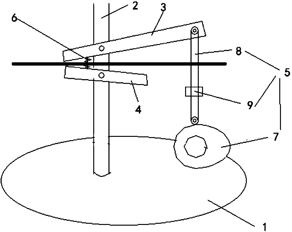
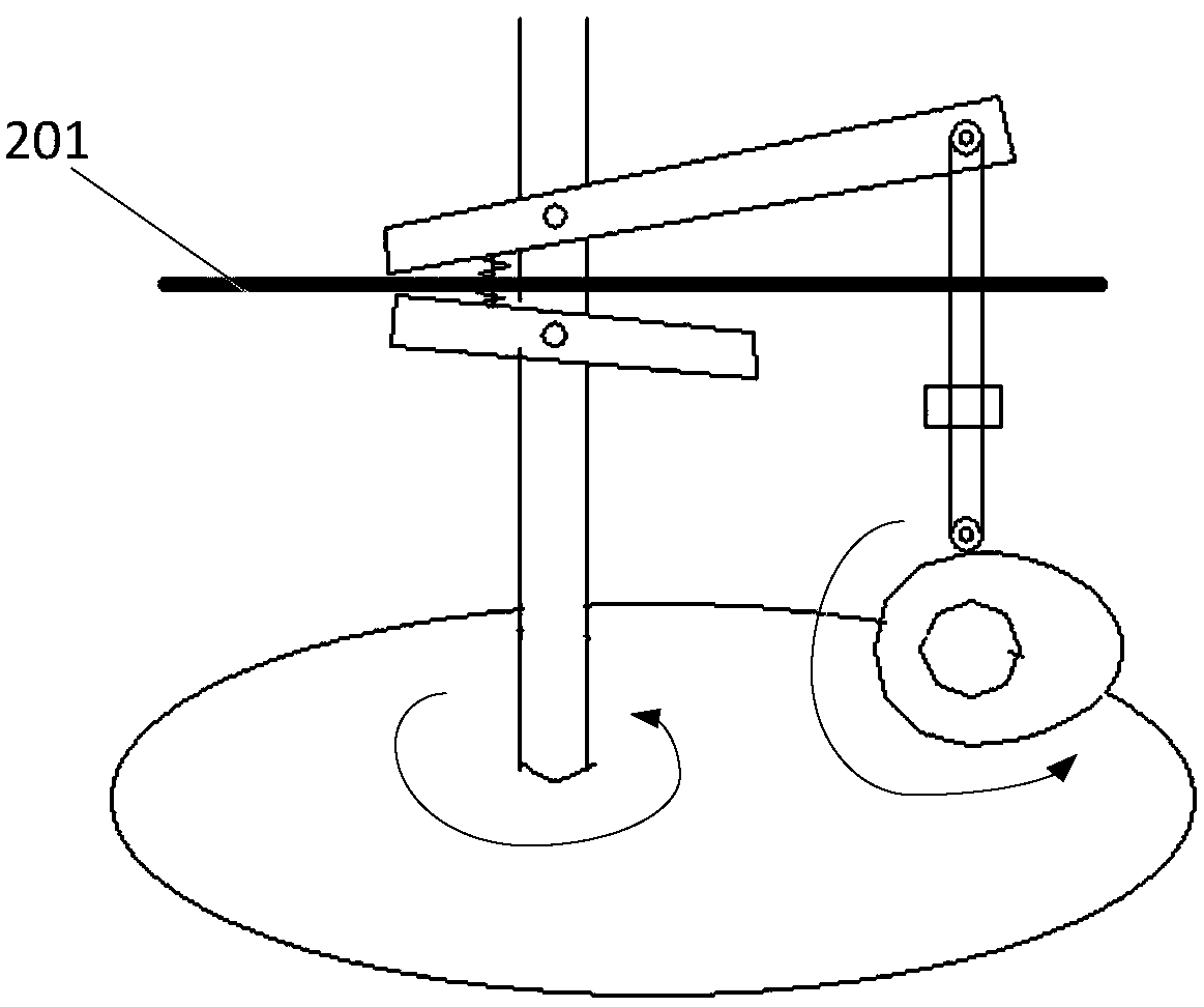
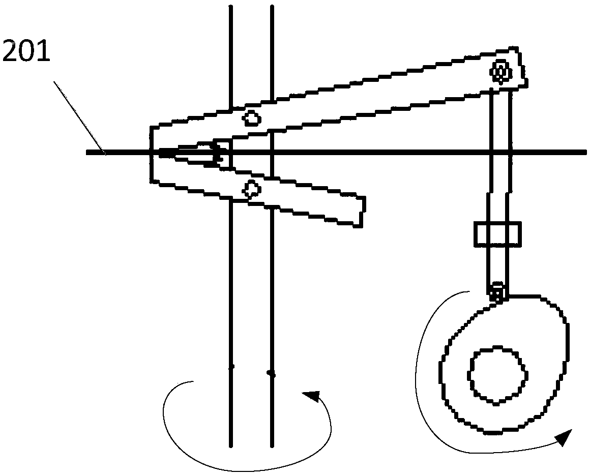
[0024] The embodiments of the present application provide a pinch device, which solves the technical problems of the pole piece transport device in the prior art that the back of the pole piece is easily contaminated with electrolyte and the polymer is easily extruded, resulting in high failure rate of the battery. Provided is a pole piece clamping device capable of improving the reliability of produced batteries.

[0025] In order to solve the above technical problems, the general idea of ​​the technical solution provided by the embodiment of the present application is as follows:

[0026] The application provides a clamping device, comprising:

[0027] a first rotating member;

[0028] a fixed pin rod, the fixed pin rod is fixed on the first rotating part so as to be able to rotate with the first rotating part;

[0029] Clamping mechanism, the clamping mechanism includes an upper splint, a lower splint and a power part; the upper splint and the lower splint are fixed on th...


PUM


Abstract

The invention discloses a pinch device, which comprises: a first rotating part; a fixed pin rod, the fixed pin rod is fixed on the first rotating part so as to be able to rotate with the first rotating part; Clamping mechanism, the clamping mechanism includes an upper splint, a lower splint and a power part; the upper splint and the lower splint are fixed on the fixed pin; the power part is connected to the upper splint and / or the The lower clamping plate is connected to control the upper clamping plate and the lower clamping plate to clamp and release the object when the upper clamping plate and the lower clamping plate rotate with the fixing pin. The device provided by the invention is used to solve the technical problems existing in the pole piece transmission device in the prior art that the back of the pole piece is easily stained with electrolyte, and the polymer is easily extruded, resulting in high failure rate of the battery. Provided is a pole piece clamping device capable of improving the reliability of produced batteries.

Description

technical field [0001] The invention relates to the technical field of battery manufacturing equipment, in particular to a pinch device. Background technique [0002] At present, one of the most critical equipment in lithium battery equipment is the coating machine. The coating machine is mainly composed of an unwinding mechanism, a coating mechanism, a baking mechanism and a winding mechanism. Whether it is transfer coating or extrusion coating On the cloth machine, the tape running process of the pole piece is usually actively pulled by the winding mechanism, and the unwinding mechanism is passively unwinded to complete the tape running of the pole piece; however, due to changes in the battery manufacturing process, especially in the solid-state lithium battery process, electrolyte coating During the process on the surface of the negative electrode sheet, since the coating material does not allow the electrolyte to be completely dried after coating and baking, that is, the...

Claims


Application Information

Patent Timeline
Patent Type & Authority Patents(China)
IPC IPC(8): H01M10/04H01M6/00
CPCH01M6/00H01M6/005H01M10/04Y02P70/50
Inventor 李昌辉向勇方刚苏兴
Owner 山西能际智能科技有限责任公司
Learn More