Plastic punching frame

A punching machine and plastic technology, applied in metal processing and other directions, can solve the problems of affecting efficiency, easy to be stuck in the plastic plate or cylinder, difficult to pull out, etc., to achieve the effect of improving efficiency

Active Publication Date: 2016-08-03
陈玲婷
View PDF5 Cites 11 Cited by
  • Summary
  • Abstract
  • Description
  • Claims
  • Application Information

AI Technical Summary

Problems solved by technology

[0002] When the existing plastic plate or cylinder is punched, it generally uses manual punching, which has low efficiency and poor effect, and after punching, the punch is easy to be stuck on the plastic plate or cylinder. Medium, difficult to pull out, affecting efficiency

Method used


Image

  • Plastic punching frame
  • Plastic punching frame
  • Plastic punching frame

Examples


Embodiment

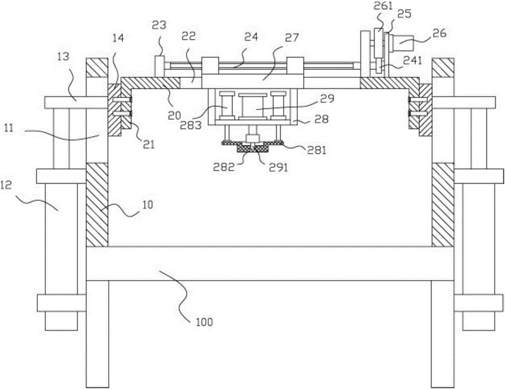
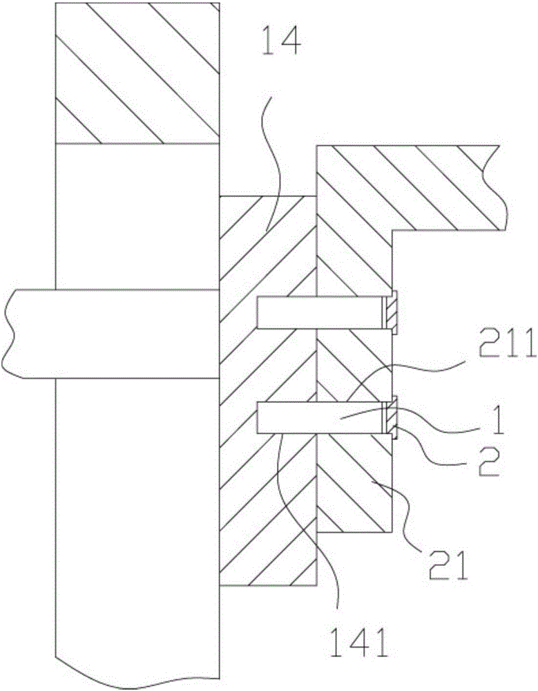
[0015] Example: see Figure 1 to Figure 3 As shown, a plastic punching frame includes a frame 100, an upper support plate 10 is fixed on both sides of the top plate of the frame 100, and the upper part of the upper support plate 10 has a vertical adjustment through groove 11. Adjusting cylinder 12 is fixed on the outer wall of support plate 10, and the end of the push rod of adjusting cylinder 12 is vertically upwards and is fixed with adjusting block 13, and adjusting block 13 is inserted and sleeved in vertically adjusting through groove 11, and on adjusting block 13 A lifting block 14 is fixed, the outer side wall of the lifting block 14 is close to the inner side wall of the upper support plate 10, the two sides of the middle transverse plate 20 have extensions 21 extending downward, and the extensions 21 are fixed on the lifting block 14;

[0016] The middle part of the middle transverse plate 20 has a transversely moving through groove 22, and the two ends of the top sur...


PUM


Abstract

The invention discloses a plastic punching frame which comprises a frame body. Upper supporting plates are fixed to the top faces of the two sides of a top plate of the frame body, and a vertical adjusting through groove is formed in the upper portion of each upper supporting plate. An adjusting cylinder is fixed to the outer side wall of each upper supporting plate, an adjusting block is fixed to a vertically upward end of a push rod of each adjusting cylinder, the adjusting blocks are inserted into the corresponding vertical adjusting through grooves, and a lifting block is fixed to each adjusting block. The outer side wall of each lifting block is tightly attached to the inner side wall of the corresponding upper supporting plate. Extending parts extending downwards are arranged on the two sides of a middle horizontal plate and fixed to the corresponding lifting blocks. A horizontal moving through groove is formed in the middle of the middle horizontal plate, connecting plates are fixed to the two ends of the top face of the middle horizontal plate, and the two ends of a transmission screw rod are hinged to the two connecting plates. The plastic punching frame can be used for automatic punching; meanwhile, the distance between a punch and a product can be adjusted; a pushing block is arranged on the punch and can prevent the punch from being clamped in the product, so that efficiency is improved.

Description

Technical field: [0001] The invention relates to the technical field of plastic processing equipment, and more specifically relates to a plastic punching frame. Background technique: [0002] When the existing plastic plate or cylinder is punched, it generally uses manual punching, which has low efficiency and poor effect, and after punching, the punch is easy to be stuck on the plastic plate or cylinder. In the middle, it is difficult to pull out, which affects efficiency. Invention content: [0003] The object of the present invention is to provide a plastic punching rack aimed at the deficiencies of the prior art, which can automatically punch holes, and at the same time, can adjust the distance between the punch and the product. It has a push block to prevent punching. The head is stuck in the product to improve efficiency. [0004] Technical solutions of the present invention are as follows: [0005] A plastic punching frame, comprising a frame, upper support plate...

Claims


Application Information

Patent Timeline
Patent Type & Authority Applications(China)
IPC IPC(8): B26F1/02B26D7/26
CPCB26D7/2628B26F1/02
Inventor 付淑珍
Owner 陈玲婷
Why Eureka
Try Eureka