
Display panel

A display panel and pixel technology, applied in the direction of optics, instruments, electrical components, etc., can solve problems such as white edges, different degrees of image brightness increase, poor display effect, etc., to achieve improved display brightness, high resolution, and good display effect Effect

Active Publication Date: 2016-08-03
NOVATEK MICROELECTRONICS CORP
View PDF3 Cites 6 Cited by
  • Summary
  • Abstract
  • Description
  • Claims
  • Application Information

AI Technical Summary

Problems solved by technology

The above situation may cause the brightness to increase differently in different parts of the image, and lead to poor display effect
For objects in the displayed image, if the brightness of the edges is excessively enhanced, abnormal display conditions such as white edges may even appear near the edges

Method used


Image

  • Display panel
  • Display panel
  • Display panel

Examples


Embodiment Construction

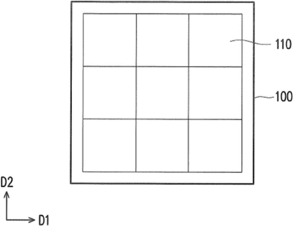
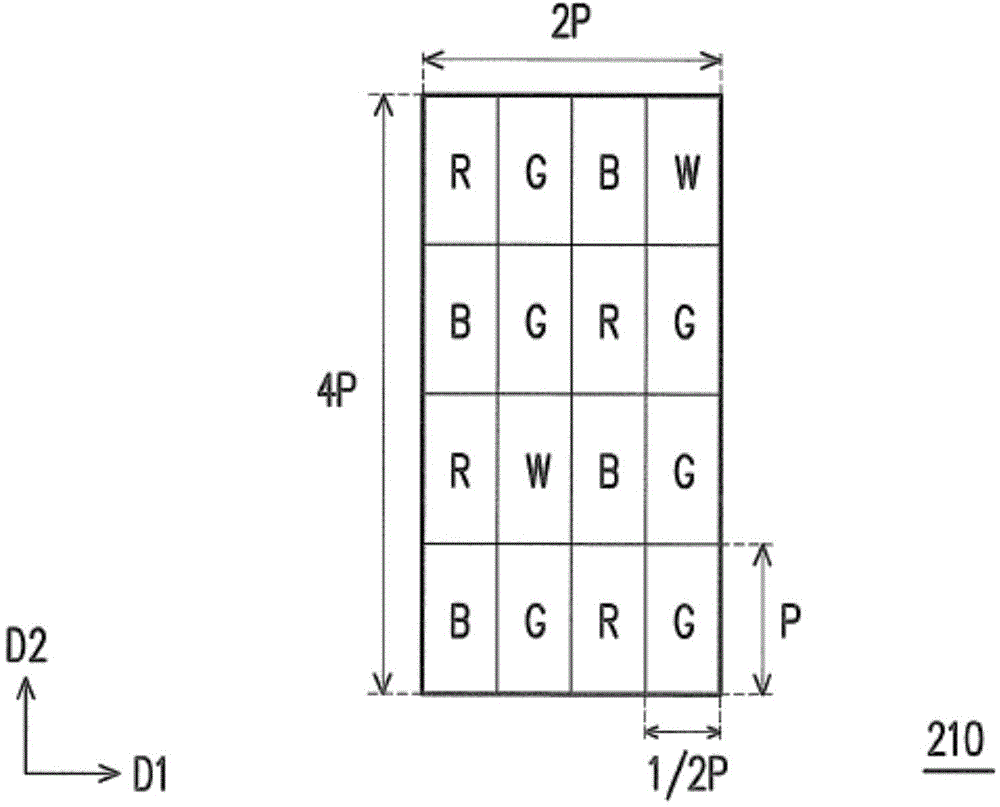
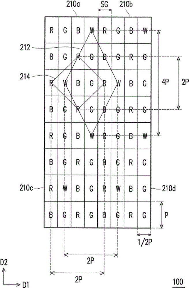
[0059] An embodiment of the present invention proposes a display panel that uses white sub-pixels to increase display brightness, and can adaptively adjust the white sub-pixels in the display panel by designing the spatial frequency arrangement (Arranging Frequency) of the white sub-pixels in each column. The above configuration makes the area of ​​the polygon surrounded by adjacent white sub-pixels at least twice the area of ​​the polygon surrounded by other color sub-pixels. In other words, adjacent white sub-pixels may be configured to be relatively dispersed. Based on the above concept, the embodiment of the present invention applies the sub-pixel rendering (Sub-Pixel Rendering, referred to as SPR) technology, and cooperates with different arrangements and designs of sub-pixels, so as to improve the abnormal display such as white borders that may appear on the edge of the object in the displayed image. Situation, and then realize the design that can be applied to high reso...


PUM


Abstract

The present invention provides a display panel, which includes a plurality of sub-pixel repeating units. The sub-pixel repeating units are repeatedly arranged on the display panel. Each sub-pixel repeating unit includes at least one first-color sub-pixel and at least one second-color sub-pixel. On the display panel, adjacent sub-pixels of the first color form a first polygon, and adjacent sub-pixels of the second color form a second polygon. The area of ​​the first polygon is at least twice the area of ​​the second polygon.

Description

technical field [0001] The present invention relates to a plane display technology, and in particular to a display panel capable of achieving good display effect under high resolution. Background technique [0002] With the vigorous development of display technology, the performance requirements of the market for display panels are moving towards high resolution, high brightness and low power consumption. However, as the resolution of display panels increases, panel makers may face the following problems. For example, the complexity of advanced pixel circuits will increase the number of thin film transistors in the layout and occupy a certain layout area, so it may be difficult to achieve high-resolution image display in a limited layout area. Furthermore, considering the process conditions, if the display process adopts different design rules (DesignRule), or is limited by the minimum safety distance of the fine metal mask (FineMetalMask), it will also affect the realizati...

Claims


Application Information

Patent Timeline
IPC IPC(8): H01L27/32G02F1/1333G02F1/167
Inventor 杨学炎杨凯闵白凤霆
Owner NOVATEK MICROELECTRONICS CORP
Learn More