A shutdown afterimage elimination circuit, its driving method, and a display device
A technology to eliminate circuit and shutdown afterimages, applied in static indicators, instruments, etc., can solve problems such as lowering the output voltage of the gate drive circuit, affecting the effect of shutdown afterimage elimination, and unable to export the pixel electrode charge in time.
- Summary
- Abstract
- Description
- Claims
- Application Information
AI Technical Summary
Problems solved by technology
Method used
Image
Examples
Embodiment 1
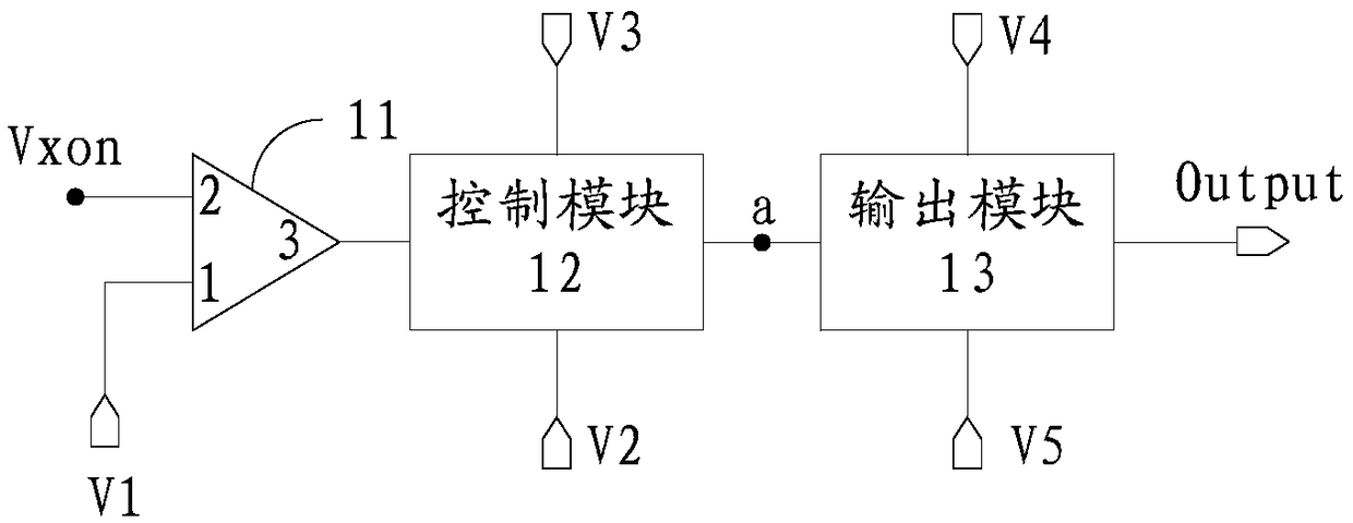
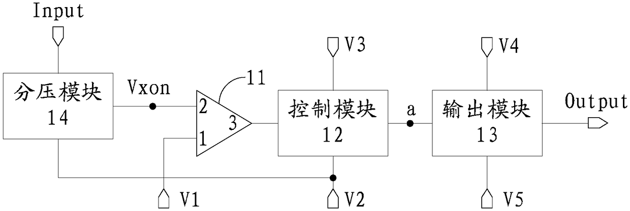
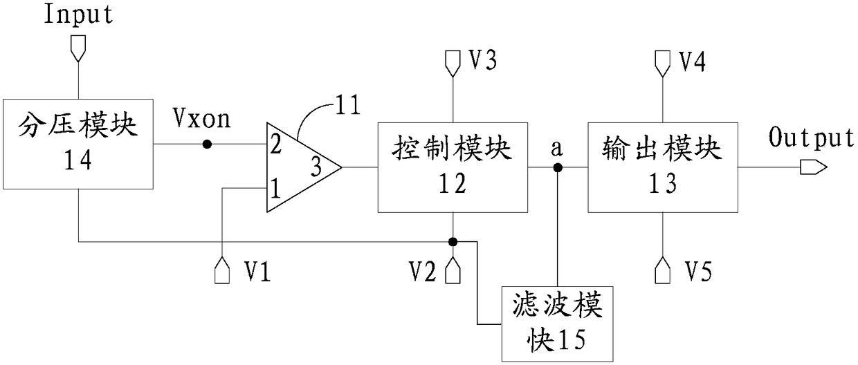
[0060] Embodiments of the present invention provide a shutdown afterimage elimination circuit, refer to figure 1 As shown, the power-off afterimage elimination circuit includes: a comparator 11 , a control module 12 and an output module 13 .
[0061] The inverting terminal 1 of the comparator 11 is connected to the first level terminal V1, and the non-inverting terminal 2 of the comparator is connected to the control voltage input terminal Vxon; When the output terminal 3 of the comparator 11 outputs a high-level voltage, when the input voltage of the non-inverting terminal 2 is less than or equal to the input voltage of the inverting terminal 1, the output terminal 3 of the comparator 11 outputs a low-level voltage.
[0062] The control module 12 is connected to the second level terminal V2, the third level terminal V4, the control node a and the output terminal 3 of the comparator 11, and is used to control the voltage of the node a when the output terminal 3 of the comparat...
Embodiment 2
[0074] An embodiment of the present invention provides a specific circuit diagram of the above-mentioned power-off afterimage elimination circuit.
[0075] Specifically, refer to Figure 4 As shown, the control module 12 in the above embodiment includes: a first transistor T1;
[0076] The first terminal of the first transistor T1 is connected to the control node a and the second level terminal V2 , the second terminal of the first transistor T1 is connected to the third level terminal V3 , and the gate of the first transistor T1 is connected to the output terminal 3 of the comparator 11 .
[0077] The output module 13 includes: a second transistor T2 and a third transistor T3;
[0078] The first terminal of the second transistor T2 is connected to the fourth level terminal V4, the second terminal of the second transistor T2 is connected to the signal output terminal Output, and the gate of the second transistor T2 is connected to the control node a;
[0079] The first termi...
Embodiment 3
[0095] An embodiment of the present invention provides another specific circuit diagram of the above-mentioned power-off residual image elimination circuit.
[0096] Specifically, refer to Figure 5 As shown, wherein, the control module 12, the voltage divider module 14 and the filter module 15 are the same as those in the second embodiment, and to avoid redundant description, they will not be described in detail in this embodiment. The difference is that the output module 13 includes: an inverting unit 131, a fourth transistor T4 and a fifth transistor T5;
[0097] The input terminal of the inverting unit 131 is connected to the control node a, the output terminal of the inverting unit 131 is connected to the gate of the fifth transistor T5, and the inverting unit 131 is used to output the output terminal of the inverting unit 131 and the input of the inverting unit 131 The phase-opposite voltage of the voltage input at the terminal;
[0098] The first terminal of the fourt...
PUM
 Abstract
Description
Claims
Application Information
 - R&D
- Intellectual Property
- Life Sciences
- Materials
- Tech Scout
- Unparalleled Data Quality
- Higher Quality Content
- 60% Fewer Hallucinations
Browse by: Latest US Patents, China's latest patents, Technical Efficacy Thesaurus, Application Domain, Technology Topic, Popular Technical Reports.
© 2025 PatSnap. All rights reserved.Legal|Privacy policy|Modern Slavery Act Transparency Statement|Sitemap|About US| Contact US: help@patsnap.com


