Automatic choke for an engine

a technology of automatic choke and engine, which is applied in the direction of machines/engines, mechanical equipment, electric control, etc., can solve the problems of engine stall, excessive hydrocarbon emissions, fouling of spark plugs, etc., and achieve the effect of reducing the number of attempts to design a small engine with automatic choke capabilities

Active Publication Date: 2006-01-31
BRIGGS & STRATTON LLC
View PDF32 Cites 37 Cited by
  • Summary
  • Abstract
  • Description
  • Claims
  • Application Information

AI Technical Summary

Benefits of technology

[0008]The present invention also provides a method of operating a choke in an internal combustion engine using exhaust heat including placing a thermally conductive assembly in direct contact with exhaust gases produced by the engine, transmitting heat from the exhaust gases to the thermally conductive assembly through a solid material, and transmitting heat from the thermally conductive assembly to a thermally responsive member in thermal contact with the thermally conductive element. The method also includes providing a linkage between the thermally responsive member and a choke operating device, and preventing the choke valve from closing completely during restarts of the engine when the temperature of the engine has reached a predetermined temperature.

Problems solved by technology

During cold starts, if the choke valve is opened too soon, the engine stalls because the fuel-air mixture is not rich enough to sustain the reaction.
If the choke remains on too long, the engine may also stumble and excessive hydrocarbon emissions and fouling of the spark plugs can occur.
Prior attempts at designing a small engine with automatic choking capabilities have been relatively unsuccessful, mostly because the designs of those chokes have been complex and thus not practical to manufacture at low cost in large numbers because the tolerances within the engine had to be very closely calculated and adjusted.

Method used


Image

  • Automatic choke for an engine
  • Automatic choke for an engine
  • Automatic choke for an engine

Examples


Embodiment Construction

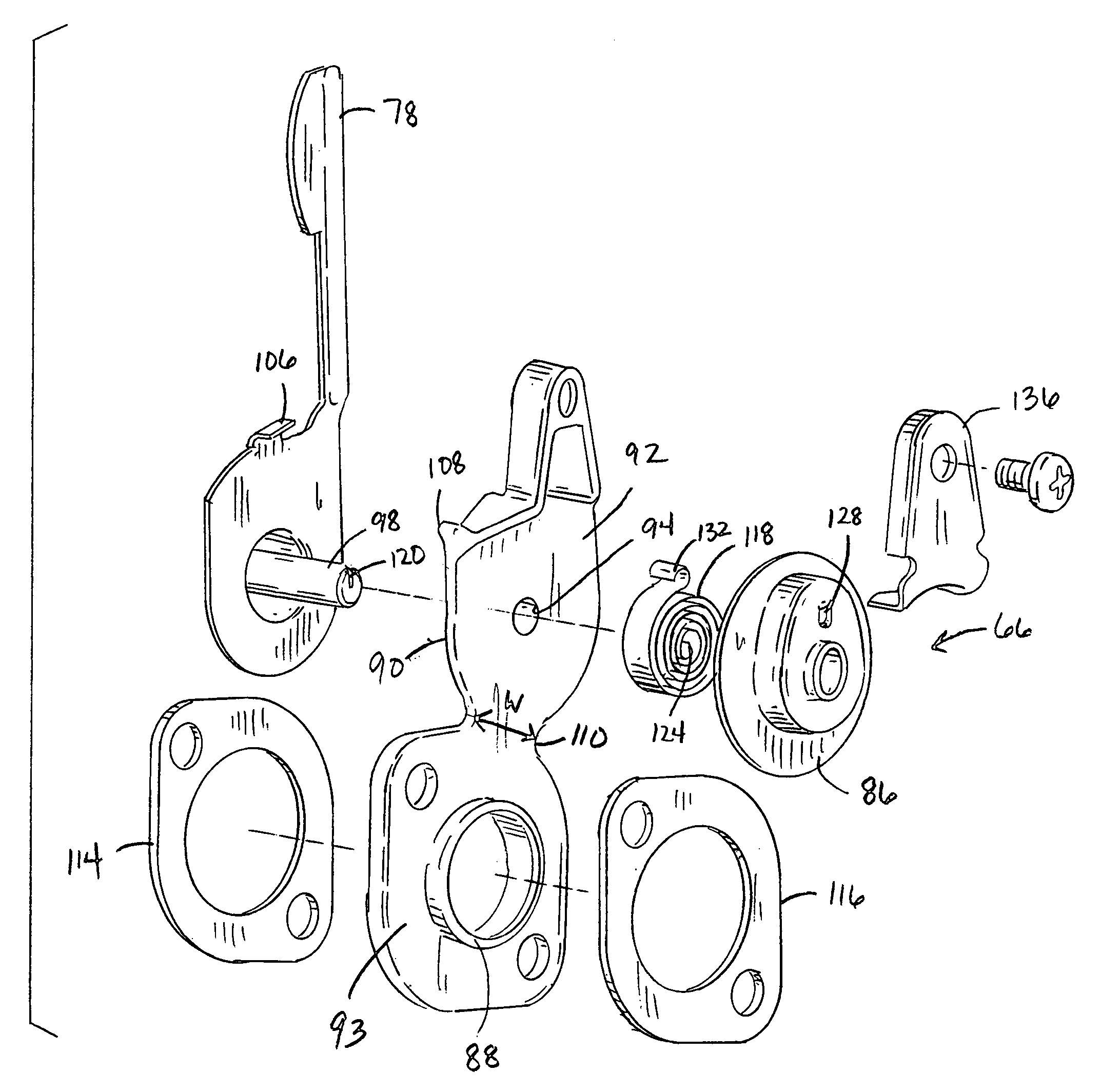
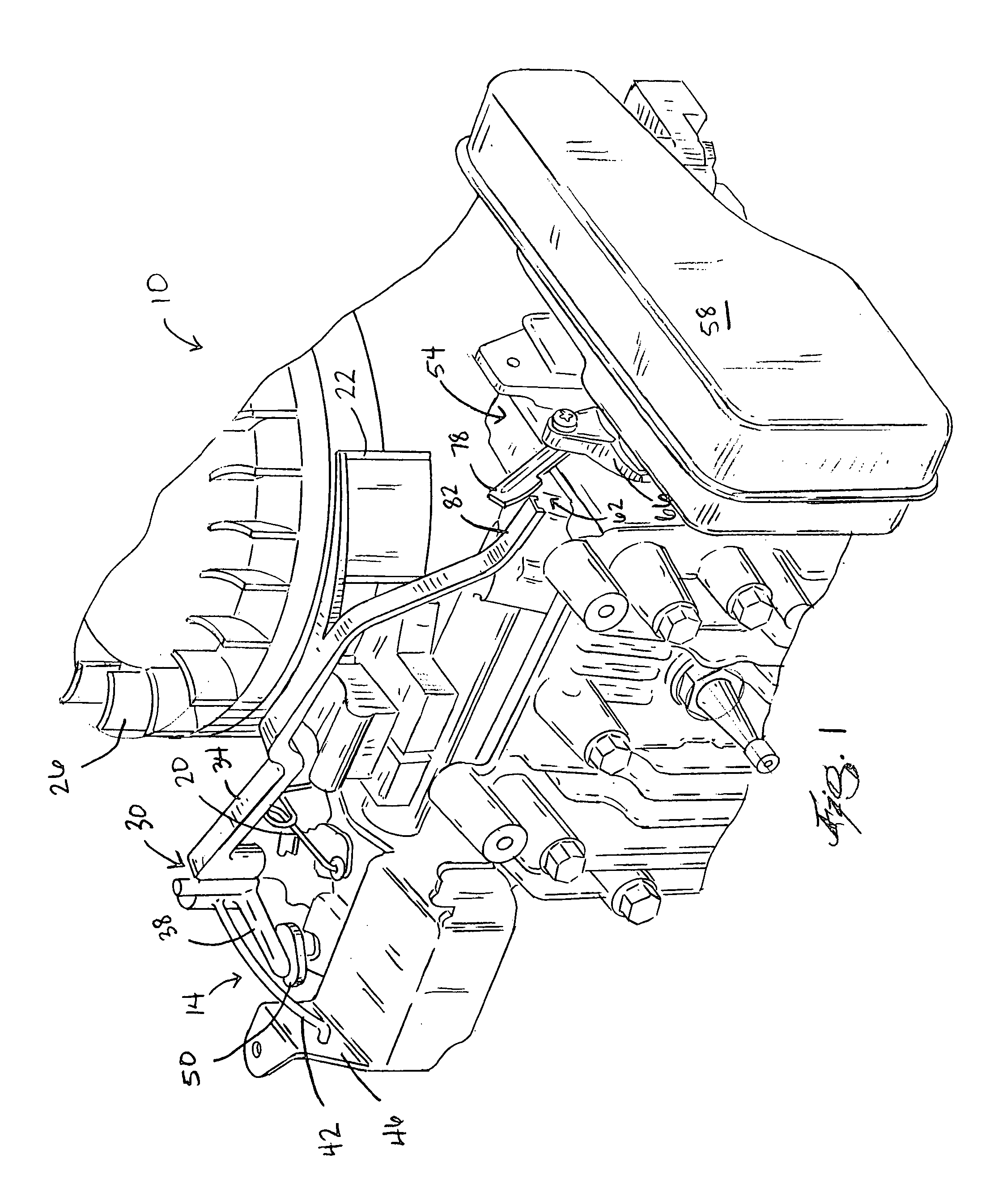
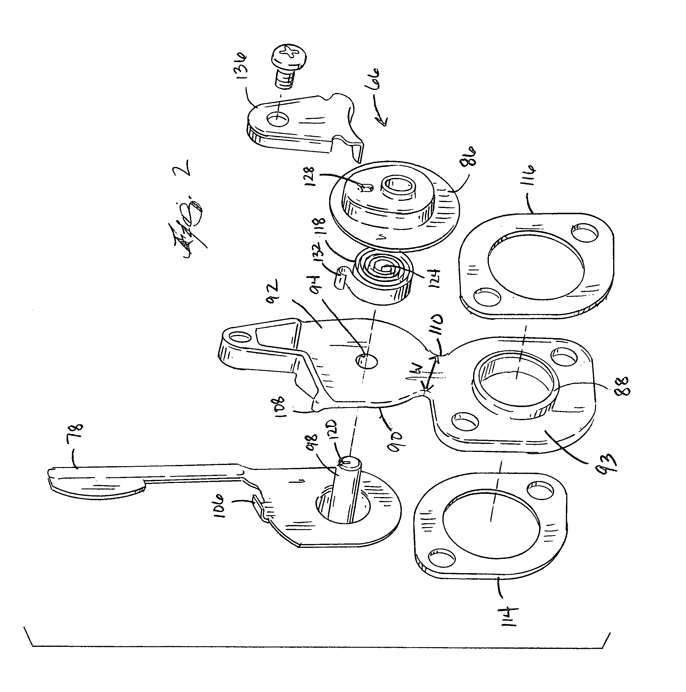
[0035]FIG. 1 illustrates an internal combustion engine 10 according to one embodiment of the present invention. The engine 10 includes a choke valve assembly 14 that includes a choke valve 18 (shown in FIG. 5) and a choke operating device. The choke operating device may operate the choke valve 18 as a function of the speed of the engine 10. In the illustrated embodiment, the choke operating device is an air vane 22. However, it would be understood by one of skill in the art that other choke operating devices could be used. For example, the choke operating device could include centrifugally mounted flyweights of an engine governor or an engine manifold pressure sensor. The engine 10 also includes a throttle linkage 20.

[0036]The air vane 22 moves in response to air flow produced by a fan 26 coupled to the engine crankshaft, and rotates with the crankshaft. In this way, the air vane 22 operates to open and / or close the choke valve as a function of the engine speed. Since the air vane 2...


PUM


Abstract

An automatic choke apparatus for use in an internal combustion engine. The choke apparatus includes a choke valve automatically operable in response to the speed of the engine, a thermally conductive assembly that conducts heat from exhaust gases produced by the engine, a thermally responsive member in thermal communication with the thermally conductive assembly, and a mechanism that moves in response to the thermally responsive member to cause the choke valve to remain in at least a partially open position during engine starting when the thermally responsive member senses a temperature above a predetermined temperature. The thermally conductive assembly at least partially surrounds the path of the exhaust gases.

Description

CROSS-REFERENCE TO RELATED APPLICATIONS[0001]This invention claims priority to U.S. Provisional Patent Application No. 60 / 491,216, filed Jul. 30, 2003, the entire contents of which is incorporated by reference herein.FIELD OF THE INVENTION[0002]This invention relates to choke assemblies for an internal combustion engine. More specifically, the invention relates to an automatic choke assembly.BACKGROUND OF THE INVENTION[0003]In small internal combustion engines utilizing a carburetor, such as those engines in a lawnmower or a snowblower, cold temperature starting of the engine requires a more fuel-rich fuel-air mixture in the intake manifold of the engine to sustain the combustion reaction. In some engines, this is done by closing a choke valve, thereby partially choking off the air supply to the engine. As the engine warms up, the choke is no longer necessary because the increased temperatures in the engine help to sustain the combustion reaction and thus the choke is opened, allowi...

Claims


Application Information

Patent Timeline
Patent Type & Authority Patents(United States)
IPC IPC(8): F02D41/00F01N1/00F01N5/02F01P5/02F02D9/02F02D11/02F02D11/04F02D17/04F02D19/02F02M1/02F02M1/10
CPCF01N1/00F02D9/02F02D11/02F02D11/04F02D17/04F02M1/02F02M1/10F01N5/02Y02T10/16F01P5/02F02D2009/0208F02D2009/0216F02D2009/0222F02D2009/0264F02D2009/0267Y02T10/12
Inventor ROTH, DAVIDDEHN, JAMES J.GUNTLY, THOMAS G.SCHULTZ, CURTISIWATA, HISAYASCHLOSSER, STEVEN R.NICKELS, TRAVISIRWIN, GREGORY D.BREITENSTEIN, KENNETH R.DETHLOFF, STEVEN A.
Owner BRIGGS & STRATTON LLC
Why Eureka
Try Eureka