
LED drive circuit capable of realizing multiple output mode setting via code dialing board

A technology of LED circuit and LED drive, which is applied in the direction of electric light source, lighting device, electrical components, etc. It can solve the problems of low efficiency, high error rate, troublesome setting, etc., and achieve the effect of high dimming accuracy and error-free

Active Publication Date: 2016-08-10
SHANGHAI ARCATA ELECTRONICS
View PDF4 Cites 2 Cited by
  • Summary
  • Abstract
  • Description
  • Claims
  • Application Information

AI Technical Summary

Problems solved by technology

[0002] In places with emergency lighting, LED current output settings, output power settings, and discharge time setting functions are also required in various situations. It is difficult for existing technologies to meet the functions of the above settings. Most manufacturers generally A single product corresponds to a single output current or a single power, and some use an external resistor to adjust the output current. In short, it is very troublesome to set up. The current emergency lighting LED lights or multi-output LED drivers use DIP switches. Through the 1-8 bit switch, dial up and down the code, and need to adjust it according to the manual, it is easy to dial wrong
Low efficiency, high error rate, and the setting of multiple output modes is not flexible enough and has no uniqueness

Method used


Image

  • LED drive circuit capable of realizing multiple output mode setting via code dialing board
  • LED drive circuit capable of realizing multiple output mode setting via code dialing board
  • LED drive circuit capable of realizing multiple output mode setting via code dialing board

Examples


Embodiment 1

[0013] The dial uses the current to indicate the desired current value of the LED lamp. The BCD code dial is coded as shown in the table below:

[0014]

[0015] It can also be implemented by inverse code, or scrambling the code.

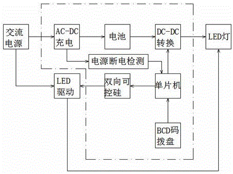
[0016] The single-chip computer calculates the output PWM modulation pulse according to the output current value corresponding to the code input by the BCD code disc, and sends it to the DC-DC conversion circuit, and the DC-DC conversion circuit controls the output current of the LED lamp.

[0017] The MCU calculates the PWM duty cycle according to the following formula:

[0018]

[0019] If the phase output current to the LED lamp is 100 mA, the duty cycle of the PWM is:

[0020]

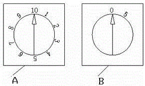
[0021] If the output current is 1000mA, the rotation positions of dial A and B are as follows: image 3 Shown:

[0022] Output current = Disk A points to digital X100+ Disk B points to digital X10

[0023] Then the output current in the above figure = 10X100...

Embodiment 2

[0025] If the output is required to be marked with power, it is the same as the aforementioned code marked with current, and the code marked with power is shown in the table below:

[0026]

[0027] The code wheel marked with power is attached Figure 4 shown.

[0028] According to the output current value corresponding to the code input by the BCD code disc, the single-chip microcomputer calculates the output PWM modulation pulse and sends it to the DC-DC conversion circuit, and the DC-DC conversion circuit controls the dimming of the LED lamp.

[0029] The MCU calculates the PWM duty cycle according to the following formula:

[0030]

[0031] The voltage of the LED is measured by a single-chip microcomputer. For the convenience of measurement, the general DC-DC needs to adopt a boost topology.

[0032] After power-on, the MCU first outputs a minimum 5% duty cycle. After measuring the LED voltage, the PWM duty cycle is calculated by the power set by the user.

[003...

Embodiment 3

[0036] If it is required to mark according to the capacity and discharge time of the battery, the code of the code disc is shown in the table below:

[0037]

[0038] code disc attached Figure 5 shown.

[0039] According to the output current value corresponding to the code input by the BCD code disc, the single-chip microcomputer calculates the output PWM modulation pulse and sends it to the DC-DC conversion circuit, and the DC-DC conversion circuit controls the dimming of the LED lamp.

[0040] The MCU calculates the PWM duty cycle according to the following formula:

[0041]

[0042] 0.9 is the coefficient, the battery voltage is the nominal voltage of the battery, the efficiency is the driving efficiency, the time is the time set on the left figure, 90 minutes corresponds to 1.5, 120 minutes corresponds to 2, the measured LED voltage is the lamp load voltage, and the maximum output current is the driving efficiency. The maximum current that can be supplied.

[00...


PUM


Abstract

The invention provides an LED drive circuit capable of realizing multiple output mode setting via a code dialing board. The LED drive circuit comprises an emergency driven LED circuit and a mains supply driven LED circuit, wherein the emergency driven LED circuit is powered via batteries, existence of alternating mains supply is detected via a one-chip microcomputer, and condition of the emergency driven LED circuit and condition of the mains supply driven LED circuit are controlled via on-off of a bidirectional silicon controlled rectifier; an LED output current, or LED output power or battery capacity and battery discharge time are set via a BCD code dialing board by the emergency driven LED circuit; codes of the BCD code dialing board correspond to a set output current, or a set output power value or set battery capacity and set battery discharge time; the corresponding codes are sent to the one-chip microcomputer via the BCD code dialing board, the one-chip microcomputer outputs modulated pulses of different duty ratios according to the codes of the BCD code dialing board and sends the same to a DC-DC direct current conversion circuit, and an aim of LED lamp multistage light modulation can be achieved.

Description

technical field [0001] The present invention relates to LED lamp lighting technology, especially in special places where emergency lighting is required in the event of a power failure, that is, battery-powered lighting or a LED driver that requires the user to set multiple current output modes by himself. LED driver. Background technique [0002] In places with emergency lighting, LED current output settings, output power settings, and discharge time setting functions are also required in various situations. It is difficult for existing technologies to meet the functions of the above settings. Most manufacturers generally A single product corresponds to a single output current or a single power, and some use an external resistor to adjust the output current. In short, it is very troublesome to set up. The current emergency lighting LED lights or multi-output LED drivers use DIP switches. Through the switch of 1-8 digits, dial up and down the code, and need to adjust accordi...

Claims


Application Information

Patent Timeline
Patent Type & Authority Applications(China)
IPC IPC(8): H05B33/08H05B44/00
CPCH05B45/00
Inventor 贵彬力戴红
Owner SHANGHAI ARCATA ELECTRONICS
Learn More