LED (Light Emitting Diode) lamp

A technology of LED lamps and LED light sources, applied in lighting devices, cooling/heating devices of lighting devices, light sources, etc., can solve the problems of difficult replacement of LED light source structures, cumbersome and complicated replacement and maintenance work, unfavorable inspection and maintenance work, etc., to achieve safety High performance, convenient and fast assembly process, convenient maintenance and replacement

Inactive Publication Date: 2016-08-17
HUBEI FANGJING ELECTRONICS TECH CO LTD
View PDF6 Cites 2 Cited by
  • Summary
  • Abstract
  • Description
  • Claims
  • Application Information

AI Technical Summary

Problems solved by technology

The structure of the existing LED lamps is traditional and old. The chassis and the LED light source structure are generally set as an integrated structure. Such a structural design requires wiring operations after the structural components are installed. The installation operation is cumbersome and prone to electric shocks, etc. Safety accidents, and such a structure cannot be disassembled, which is not conducive to later inspection and maintenance work, and once the LED light source is damaged, it is easy to cause the entire LED lamp to be scrapped, which is not energy-saving and environmentally friendly. The light source structure is difficult to replace, that is to say, it is difficult for users to flexibly change various light source bodies with different luminous effects according to actual needs, and the replacement and maintenance work is cumbersome and complicated

Method used


Image

  • LED (Light Emitting Diode) lamp
  • LED (Light Emitting Diode) lamp
  • LED (Light Emitting Diode) lamp

Examples


Embodiment Construction

[0014] It should be understood that the specific embodiments described here are only used to explain the present invention, not to limit the present invention.

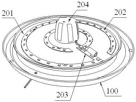
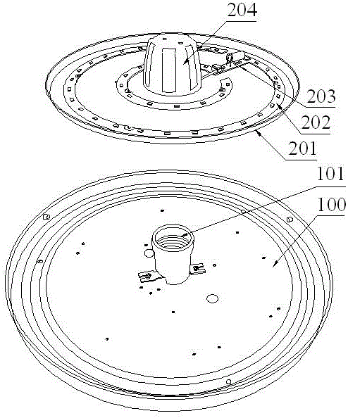
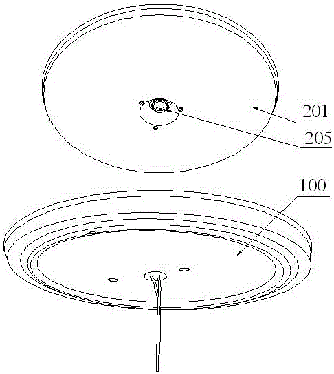
[0015] refer to Figure 1 to Figure 3 , an embodiment of an LED lamp of the present invention is proposed, including an installation chassis 100, a lamp holder 101 fixed on the installation chassis 100, a light source body installed and fixed in the lamp holder 101 and energized, and a cover arranged on the light source body The light-transmitting cover, the light source body includes a light source chassis 201, an LED light source structure 202 fixed on the light source chassis 201, a driving circuit board 203 electrically connected to the LED light source structure 202, and a light source chassis 201. Insert the insulating sleeve 204 of the lamp base 101 , the lamp cap nut 205 which is arranged in the insulating sleeve 204 and is electrically connected with the drive circuit board 203 and can be screwed into the lam...


PUM


Abstract

The invention discloses an LED (Light Emitting Diode) lamp. The LED lamp comprises a mounting base plate, a lamp holder seat which is fixedly arranged on the mounting base plate, a light source body which is mounted and fixed in the lamp holder seat and is electrified, and a light transmitting cover which covers the light source body, wherein the light source body comprises a light source base plate, an LED light source structure which is fixedly arranged on the light source base plate, a driving circuit board which is electrically connected with the LED light source structure, an insulating sleeve seat which is arranged at the central position of the light source base plate and can be used for containing the lamp holder seat, and a lamp holder nut which is arranged in the insulating sleeve seat, is electrically connected with the driving circuit board and can be mounted in the lamp holder seat in a screw joint manner so as to be electrified with the lamp holder seat; and when the light source body is mounted, the insulating sleeve seat sleeves the lamp holder seat and the insulating sleeve seat is rotated so that the lamp holder nut is mounted in the lamp holder seat in the screw joint manner so as to be electrified with the lamp holder seat.

Description

technical field [0001] The invention relates to the technical field of lamps, in particular to an LED lamp. Background technique [0002] LED lamps are widely used because of their high lighting brightness, safety, energy saving and environmental protection. The structure of the existing LED lamps is traditional and old. The chassis and the LED light source structure are generally set as an integrated structure. Such a structural design requires wiring operations after the structural components are installed. The installation operation is cumbersome and prone to electric shocks, etc. Safety accidents, and such a structure cannot be disassembled, which is not conducive to later inspection and maintenance work, and once the LED light source is damaged, it is easy to cause the entire LED lamp to be scrapped, which is not energy-saving and environmentally friendly. The light source structure is difficult to replace, that is to say, it is difficult for users to flexibly change v...

Claims


Application Information

Patent Timeline
Patent Type & Authority Applications(China)
IPC IPC(8): F21K9/00F21V17/12F21V19/04F21V25/00F21V29/89F21Y115/10
CPCF21K9/00F21V17/12F21V25/00F21V29/89
Inventor 赖俊彬
Owner HUBEI FANGJING ELECTRONICS TECH CO LTD
Why Eureka
Try Eureka