A transmission unit detector imaging and electrical parameter testing system

A technology of unit detectors and electrical parameters, applied in the directions of measuring electricity, measuring electrical variables, and testing optical properties, etc., can solve problems such as verification and inability to scan imaging performance at the same time, achieve low cost, strong application and market value, and realize instrumental effect

Inactive Publication Date: 2019-06-04
THE 41ST INST OF CHINA ELECTRONICS TECH GRP
View PDF15 Cites 0 Cited by
  • Summary
  • Abstract
  • Description
  • Claims
  • Application Information

AI Technical Summary

Problems solved by technology

[0005] Aiming at the problem that existing unit detectors cannot scan imaging and perform performance verification at the same time, the present invention provides a transmissive unit detector imaging and electrical parameter testing system

Method used


Image

  • A transmission unit detector imaging and electrical parameter testing system
  • A transmission unit detector imaging and electrical parameter testing system

Examples


Embodiment 1

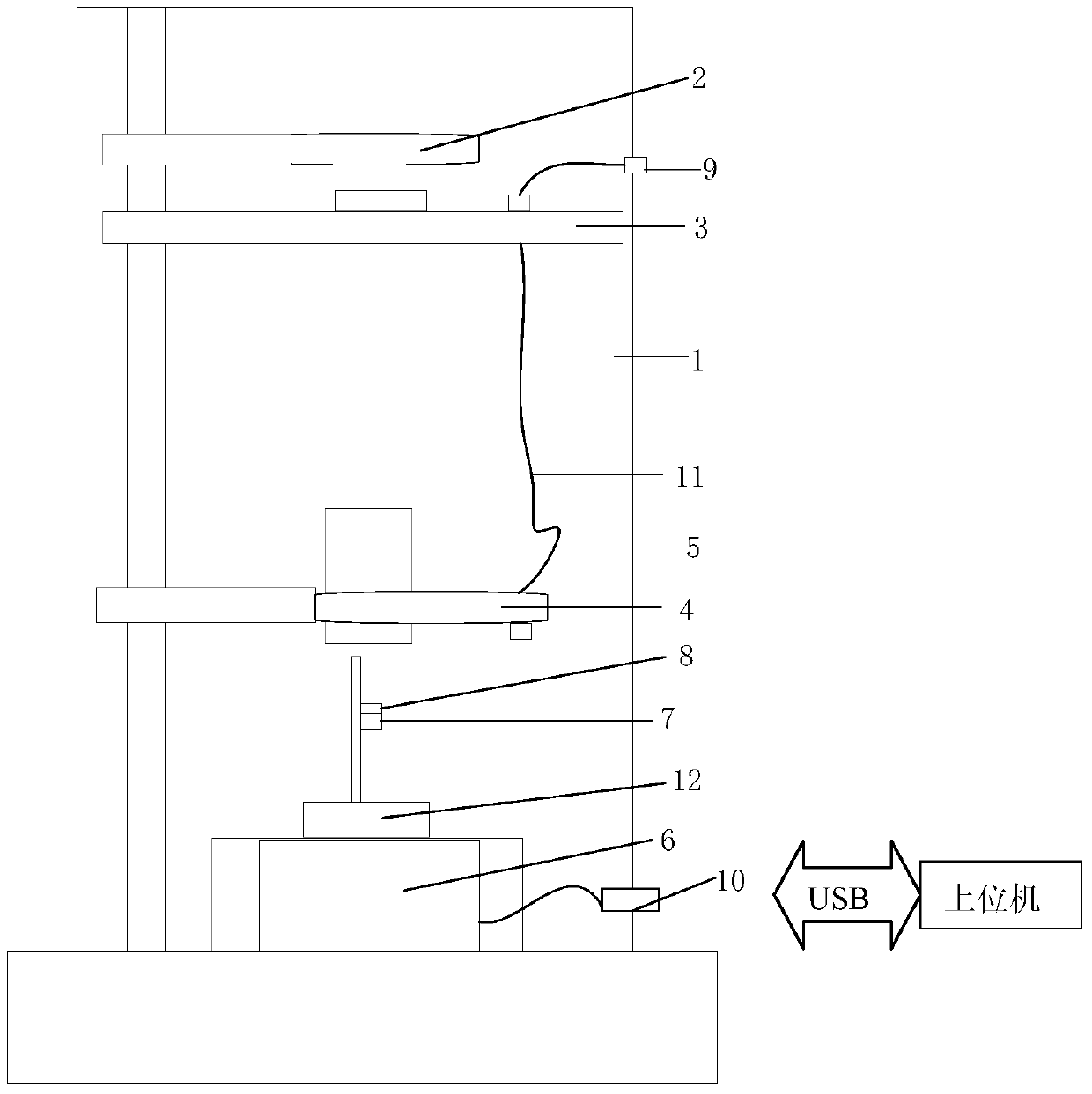
[0020] An imaging operation method of a transmission type unit detector, comprising:

[0021] Step 1: The three-dimensional scanning platform automatically controls the focusing operation, completes the focusing operation of the detector in the direction of the Z axis, uses the motor control to complete the adjustment of the stage and the rotating platform, and the stage rotates to the state where the light source is fully open. When the value collected by the AD sampling module is the maximum, it is confirmed that the system focus is completed;

[0022] Step 2: Place the target object on the stage, the stage motor rotates the target object to the optical path, and the three-dimensional scanning platform uses the X-axis and Y-axis to complete the imaging and scanning of the two-dimensional plane;

[0023] Step 3: Carry out formal imaging to display the acquisition process. The data transmission flow is as follows: the detector converts the optical signal on the focal plane int...

Embodiment 2

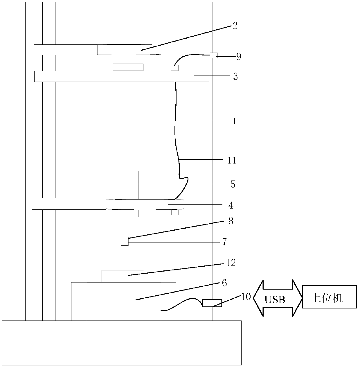
[0026] An operation method for testing electrical parameters of a transmissive unit detector, comprising:

[0027] Step 1: The 3D scanning platform automatically controls the focusing operation, and uses the motor control to complete the adjustment of the stage and the rotating platform, so that the optical fiber light source interface is aligned with the collimator. When the value collected by the AD sampling module is the largest, it is confirmed as The system focus is completed;

[0028] Step 2: The operation interface is in the state of electrical parameter testing. After the system completes the automatic focusing, the formal parameter testing process is carried out. By adjusting the wavelength, power, pulse width and other parameters of the fiber optic light source, it enters the collimator and finally the detector The light source is an optical signal with known parameters.

[0029] The flow direction of data transmission is: the detector converts the optical signal on...


PUM


Abstract

The invention provides a transmission-type unit detector imaging and electrical parameter testing system, including a shielding cover and a host computer, a space light source is arranged in the shielding cover, a loading platform is arranged under the space light source, and a loading platform is arranged under the loading platform. There is a rotating platform, a lens is installed on the rotating platform, a three-dimensional scanning platform is arranged under the rotating platform, a detector is connected to the three-dimensional scanning platform, and a collimator is connected to the detector. The invention adopts a three-dimensional scanning array to complete the focusing operation of the detector in the Z-axis direction, and completes the imaging and scanning process of the two-dimensional plane by using the X-axis and Y-axis, with simple control, low cost, and real-time calibration of the fixed-focus position At the same time, the system can use a simple power-adjustable transmission optical path to complete the test of unit detector parameters, including dark current, responsivity, breakdown voltage and other detector performance parameters.

Description

technical field [0001] The invention relates to the field of unit detectors, in particular to a transmission-type unit detector imaging and electrical parameter testing system. Background technique [0002] With the development of large-area array detectors, there are almost no imaging systems using unit detectors. However, in order to effectively integrate large-array detectors, the performance verification of unit photosensitive units has become a thorny problem. In order to verify the imaging performance of the designed unit detector or external imaging display, the production and development of detectors and the research and development of photosensitive materials often need to design complex and high-cost optical path systems and two-dimensional scanning array platforms. At the same time, they need to be equipped with other systems. The test of the detector parameters is completed, so the current system can only display images without synchronous analysis of the real-ti...

Claims


Application Information

Patent Timeline
Patent Type & Authority Patents(China)
IPC IPC(8): G01R31/00G01M11/02
CPCG01M11/02G01R31/00
Inventor 刘磊江升韩顺利闫继送刘加庆吕子敬
Owner THE 41ST INST OF CHINA ELECTRONICS TECH GRP
Why Eureka
Try Eureka