Precise fiber optic delay line and precise delay control method based on corner cube

A technology of fiber optic delay line and corner cube prism, which is applied in the coupling and coating of mirrors and optical waveguides, can solve the problems of high precision and low insertion loss, achieve small insertion loss, reasonable design, and realize instrumentation and engineering effect

Inactive Publication Date: 2015-11-18
INST OF FLUID PHYSICS CHINA ACAD OF ENG PHYSICS
View PDF4 Cites 0 Cited by
  • Summary
  • Abstract
  • Description
  • Claims
  • Application Information

AI Technical Summary

Problems solved by technology

[0004] An object of the present invention is to provide a precision optical fiber delay line based on a corner cube, which solves the problem that it is difficult to simultaneously achieve high precision and low insertion loss in the prior art

Method used


Image

  • Precise fiber optic delay line and precise delay control method based on corner cube
  • Precise fiber optic delay line and precise delay control method based on corner cube
  • Precise fiber optic delay line and precise delay control method based on corner cube

Examples


Embodiment Construction

[0027] The present invention will be further described below in combination with specific embodiments and accompanying drawings.

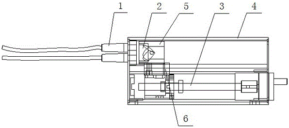
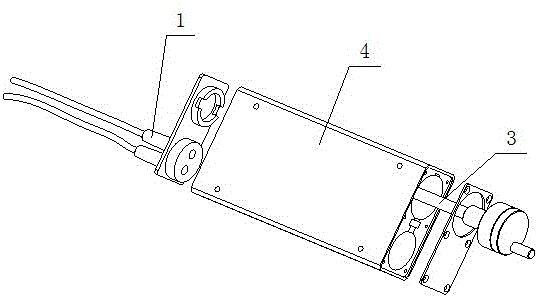
[0028] like Figure 1 to Figure 8 As shown, a precision fiber delay line based on a corner cube prism, including a fiber collimator 1, a corner cube prism 2, a ball screw 3 and a packaging case 4, two fiber optic collimators 1 are installed in parallel on the packaging case 4 At one end, the corner cube 2 and the ball screw 3 are placed in the package housing 4, the chord surface of the corner cube 2 is opposite to the light exit port of the fiber collimator 1, and the chord surface 21 of the corner cube 2 is coated with a pair of Anti-reflection coating with light wavelength of 1550nm, three cones 22 are coated with anti-reflection coating with light wavelength of 1550nm, the whole reflectivity reaches more than 95%, the corner cube prism 2 is fixed in the lens frame 5, and the lens frame 5 passes through the connecting block 6 Connect with ball ...


PUM

PropertyMeasurementUnit
wavelengthaaaaaaaaaa

Abstract

The invention discloses a pyramid-prism-based precise FDL. The pyramid-prism-based precise FDL comprises fiber collimators, a pyramid prism, a ball screw and a seal casing. Two fiber collimators are mounted at one end of the seal casing, the pyramid prism and the ball screw are disposed inside the seal casing, the chord surface face of the pyramid prism faces to the light output ports of the fiber collimators and coated with an antireflection film, the three conical surface of the pyramid prism are coated with reflection enhancement films, the pyramid prism is fixedly arranged in a lens holder, and the lens holder is connected with the ball screw through a connection block. The pyramid-prism-based precise FDL is reasonable in design, easy to use, high in delay precision, small in insertion loss and simple in structure and can help achieve instrumentation and engineerization.

Description

technical field [0001] The invention relates to the technical field of high-precision time delay, in particular to a precision optical fiber delay line based on a corner cube prism and a method for precise delay control. Background technique [0002] Optical precision delay is mainly used in phased array radar, optical sampling and other fields. Especially in optical sampling, the sampling accuracy is directly determined by the delay accuracy. At present, the optical delay is mainly through stretching the optical fiber and using a prism for reflection. Among them, the stretching optical fiber method has disadvantages such as large loss, uncontrollable, and unrecoverable; the free space delay method has strong operability, and a prism is generally used. Reflection, this requires very high precision for the adjustment of the prism, and the insertion loss is relatively large during the forward and backward movement. At the same time, considering the movement accuracy of the me...

Claims


Application Information

Patent Timeline
Patent Type & Authority Patents(China)
IPC IPC(8): G02B6/28G02B6/32G02B1/11G02B5/08
Inventor 陶世兴赵新才胡腾李泽仁彭其先王荣波刘宁文
Owner INST OF FLUID PHYSICS CHINA ACAD OF ENG PHYSICS
Why Eureka
Try Eureka